Integrated automation transformer substation

A comprehensive automation and substation technology, applied in the direction of panel/switch station circuit devices, busbar/line layout, etc., can solve problems such as hidden safety hazards, poor reliability, and backward functions, so as to improve equipment operation reliability and improve sustainable competitiveness. , the effect of improving the level of intelligence

Inactive Publication Date: 2014-06-11
SHANGHAI MUNICIPAL ELECTRIC POWER CO
View PDF4 Cites 2 Cited by
  • Summary
  • Abstract
  • Description
  • Claims
  • Application Information

AI Technical Summary

Problems solved by technology

[0006] However, in the above-mentioned existing substation, the 35kV switch compartment is assembled, and there are potential safety hazards
The 10kV switchgear equipment in the station is backward, the relay protection is electromagnetic, using RTU, the AC and DC system has been running for more than 10 years, and there is no substation automation system
The equipment in the station is outdated, its functions are backward, and there are many equipment failures, which cannot meet the operation needs
At the same time, the microcomputer five-prevention system is backward, without SF6 gas alarm and fire alarm system, which is not conducive to the safe operation of substations, poor reliability, unable to adapt to the construction and development of smart grids, and difficult to meet the functional needs of substation automation systems under the conditions of large-scale operation of power grids

Method used


Image

  • Integrated automation transformer substation
  • Integrated automation transformer substation
  • Integrated automation transformer substation

Examples


Embodiment Construction

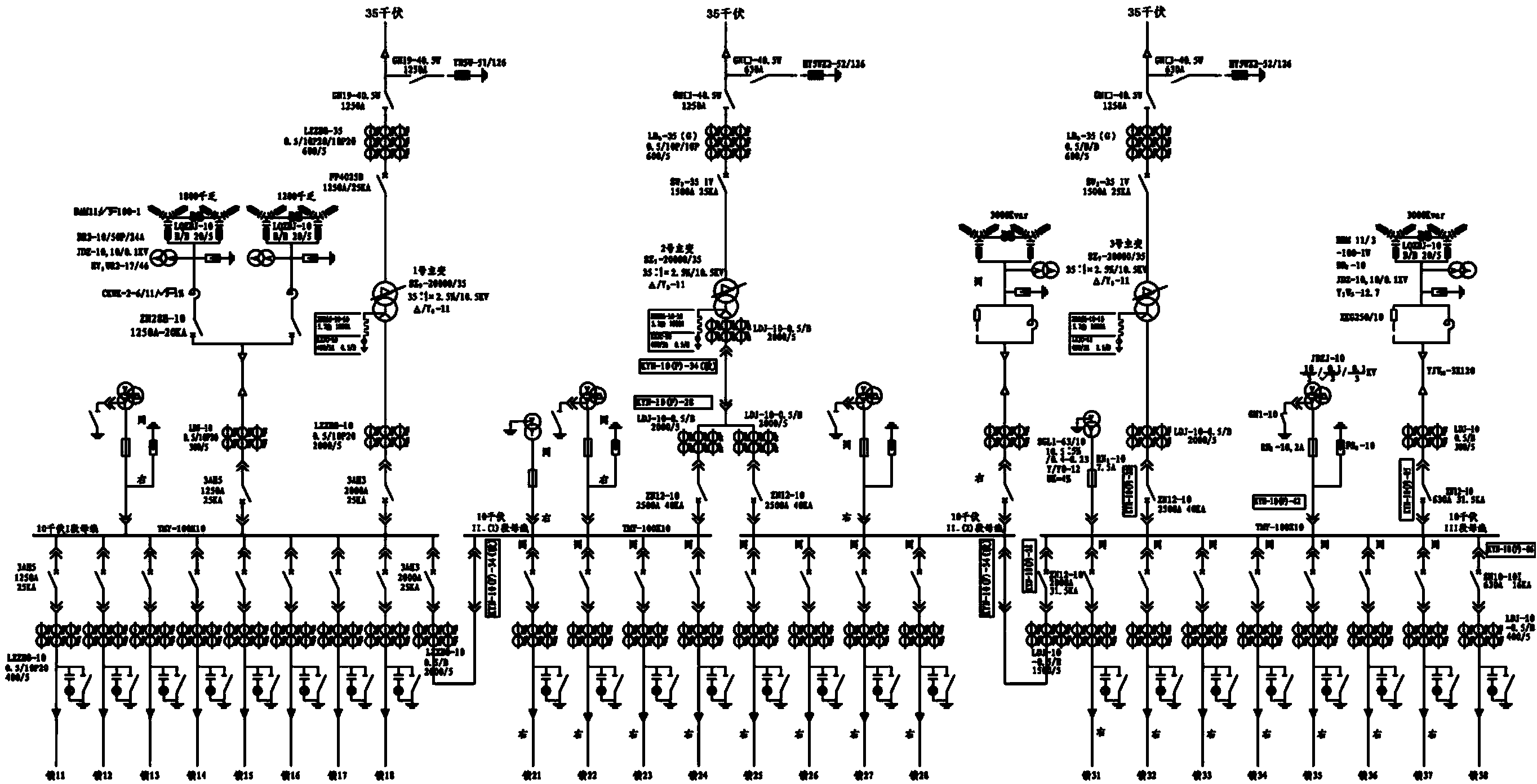
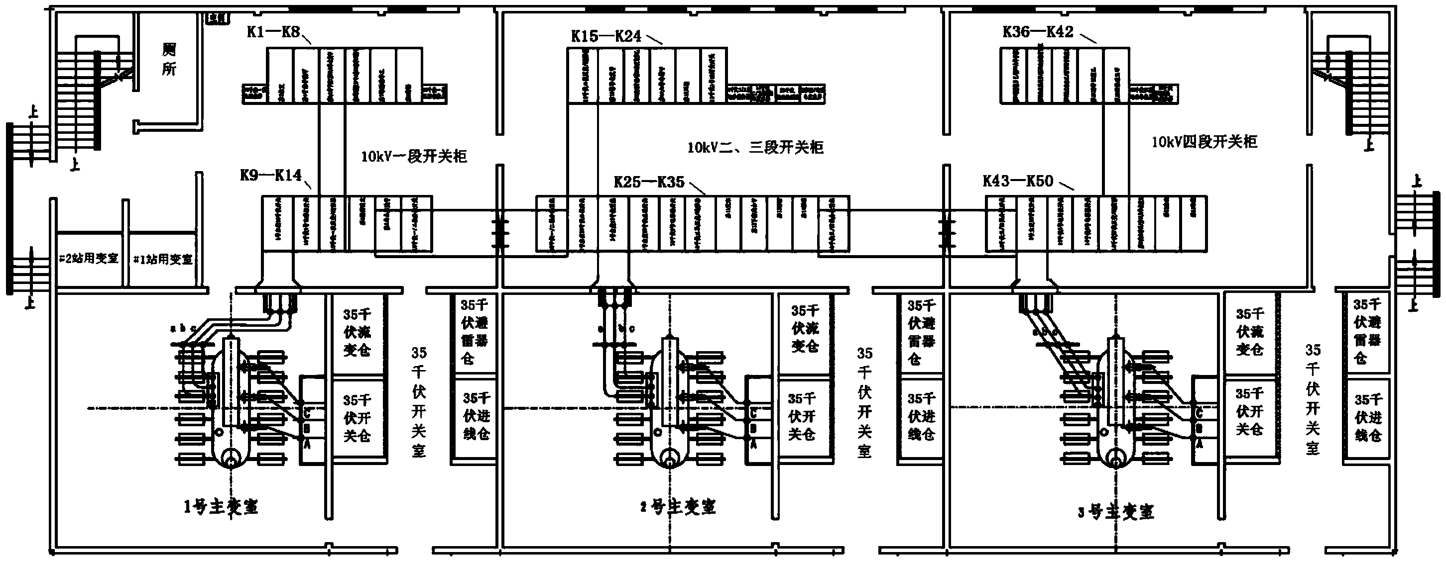
[0035] like Figure 5 , Figure 5A As shown, the present invention provides a comprehensive automatic substation, which adopts the wiring mode of line transformer group. The first 35kV incoming line supplies power to No. 1 main transformer, a 10kV busbar and its eight outgoing lines; the second 35kV incoming line is No. 2 main transformer. Transformer, 10kV two-section busbar and its four outgoing lines and three-section busbar and its four outgoing lines supply power; the third 35kV incoming line supplies power to No. 3 main transformer, 10kV four-section busbar and its eight outgoing lines.

[0036]Three 35kV incoming line switches Q1 are installed in the 35kV / 10kV switch room, using SF6 circuit breakers and equipped with spring operating mechanisms to connect or disconnect the corresponding 35kV power incoming lines. Each 35kV incoming line is connected to each 35kV incoming line switch Q1 through the corresponding 35kV current transformer, and a 35kV incoming line arreste...


PUM


Abstract

The invention provides an integrated automation transformer substation. A first 35kV inlet wire is communicated with a first 35kV inlet wire switch, a No.1 main transformer, a first 10kV main transformer switch, a 10kV first section bus and a plurality of outlet wires thereof, a second 35kV inlet wire is communicated with a second 35kV inlet wire switch and a No.2 main transformer, then is communicated with a second 10kV main transformer switch, a 10kV second section bus and a plurality of outlet wires thereof, a third 10kV main transformer switch, a third section bus and a plurality of outlet wires thereof respectively, a first section switch and a lead are arranged between the first section bus and the second section bus, a third 35kV inlet wire is communicated with a third 35kV inlet wire switch, a No.3 main transformer, a fourth 10kV main transformer switch, a 10kV fourth section bus and a plurality of outlet wires thereof, a second section switch and another lead are arranged between the third section bus and the fourth section bus, and a transformer for a first station and a transformer for a second station are connected with the second section bus and the fourth section bus respectively through corresponding transformer switches for the stations, so as to supply power to the whole transformer substation. The integrated automation transformer substation can adapt to the controlled operation requirement of modern transformer substation, and improve the equipment operation reliability and the intelligent level of a power grid.

Description

technical field [0001] The invention relates to the field of electric power supply, in particular to a comprehensive automatic substation. Background technique [0002] like figure 1 Shown is the electrical wiring diagram of the existing substation. The 35kV substation has three 35kV power incoming lines with three 20000kVA transformers; the 35kV system is connected to the line transformer group and installed at intervals; the 10kV system is connected to three busbars and four sections. [0003] Three 35kV power supply lines are connected to No. 1, No. 2 and No. 3 main transformers through their respective isolation switches, 35kV current transformers, and 35kV switches; each power supply line is equipped with lightning arresters. The No. 1 main transformer supplies power to the 10kV first-stage busbar and its 8 subordinate outgoing lines through the corresponding 10kV switch; The 4 subordinate outgoing lines supply power; the No. 3 main transformer supplies power to the ...

Claims


Application Information

Patent Timeline
Patent Type & Authority Applications(China)
IPC IPC(8): H02B1/24H02B1/20
Inventor 谢邦鹏游兆阳孙阳盛王何舟陈雪瓅冯蓓艳都泓蔚于盛楠
Owner SHANGHAI MUNICIPAL ELECTRIC POWER CO
Why Eureka
Try Eureka