Shield structure for electronic apparatus

A technology of electronic equipment and shielding structure, which is applied in the fields of magnetic field/electric field shielding, electrography, electrical components, etc., can solve the problems of difficulty in forming a connection part, increase in cost, increase in cost of wiring substrate, etc., and improve assembly workability. , cost reduction, the effect of improving the freedom of wiring

Active Publication Date: 2014-06-11
KYOCERA DOCUMENT SOLUTIONS INC
View PDF6 Cites 3 Cited by
  • Summary
  • Abstract
  • Description
  • Claims
  • Application Information

AI Technical Summary

Problems solved by technology

[0006] However, in the image forming apparatus, the drive system control board and the image processing board are composed of separate wiring boards. When these separate wiring boards are mounted on the main body frame, the four corners of each wiring board need to be installed with four screws. Therefore, a total of eight screws are required for the two wiring boards, and there is a problem that the number of screws and the installation workload increase.
Moreover, there is also the problem of increasing the wiring harness
In addition, when the drive system control board and the image processing board are separate wiring boards, there are also problems such as an increase in the cost of the wiring board of the entire device.
[0007] Therefore, in order to reduce the cost of the wiring board and the wiring harness, it is conceivable to integrate the drive system control board and the image processing board. However, the integration of the two wiring boards can reduce the number of screws and wiring harnesses, but the overall coverage of the integrated wiring board The problem of increasing the cost due to the increase of the shielding box
[0008] In addition, in the shielding structure known in the past, since the entire wiring board 30 is covered by the box body 101, it is necessary to provide a wiring harness for connecting with the driving components in the device, or to form a hole for the wiring harness, so there is a problem that the noise radiation cannot be stably reduced. The problem
[0009] In addition, it is not easy to form the connecting parts 13 and 23 by deep drawing the main body 101A and the cover part 101B of the box body 101 made of metal plates, and there is a problem that the arrangement interval of the screws 21 is significantly restricted.
[0010] In addition, although a shield can can be used as a part that shields only a small area of ​​the noise generation source, there is a problem that the amount of work increases because it needs to be soldered to the substrate
In addition, when shielding the CPU and ASIC with a shielding can, there is a possibility of damage to the CPU and ASIC due to temperature rise, so it is necessary to install a radiator as a cooling device or use a fan for forced cooling, resulting in complicated structure and cost. raised questions

Method used


Image

  • Shield structure for electronic apparatus
  • Shield structure for electronic apparatus
  • Shield structure for electronic apparatus

Examples


Embodiment Construction

[0021] Embodiments of the present invention will be described below with reference to the drawings.

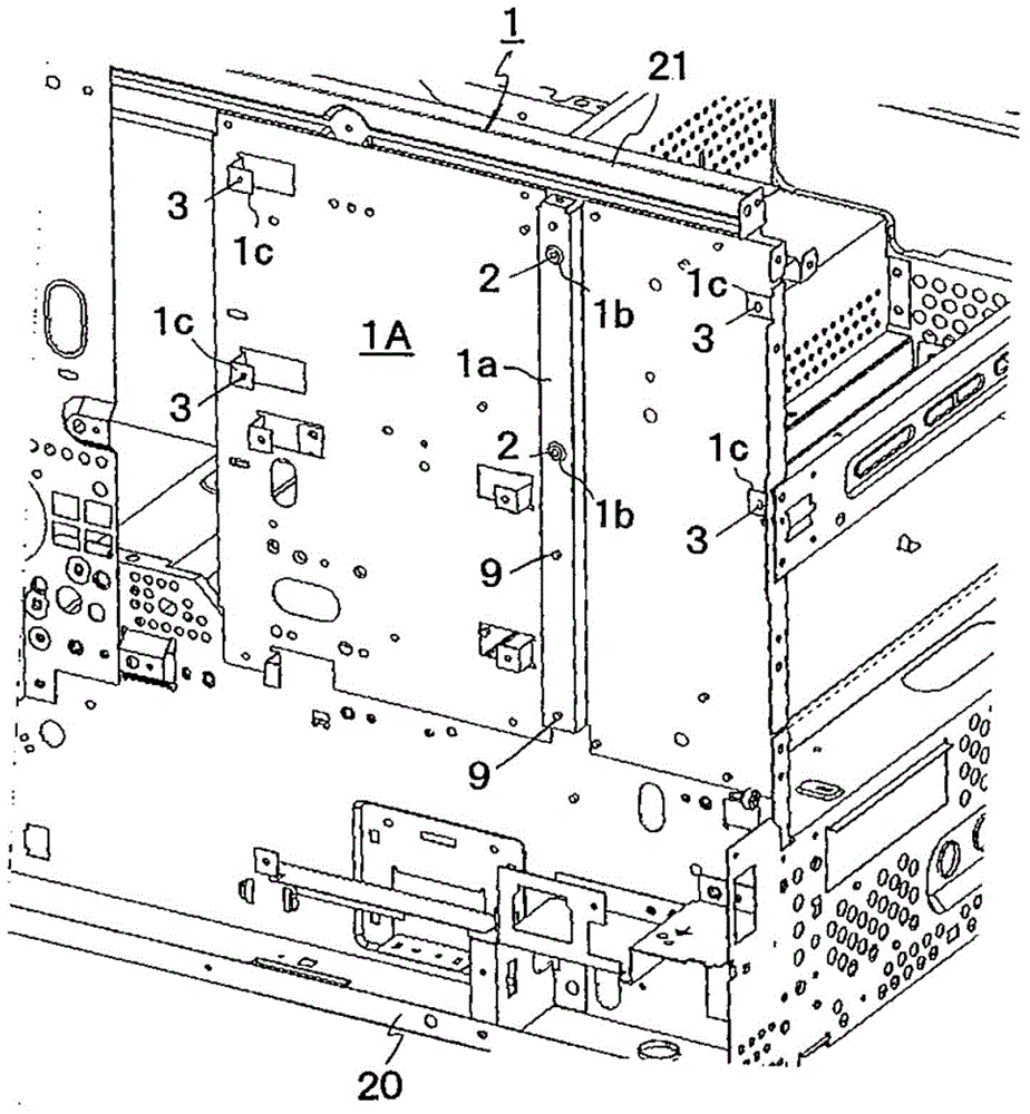
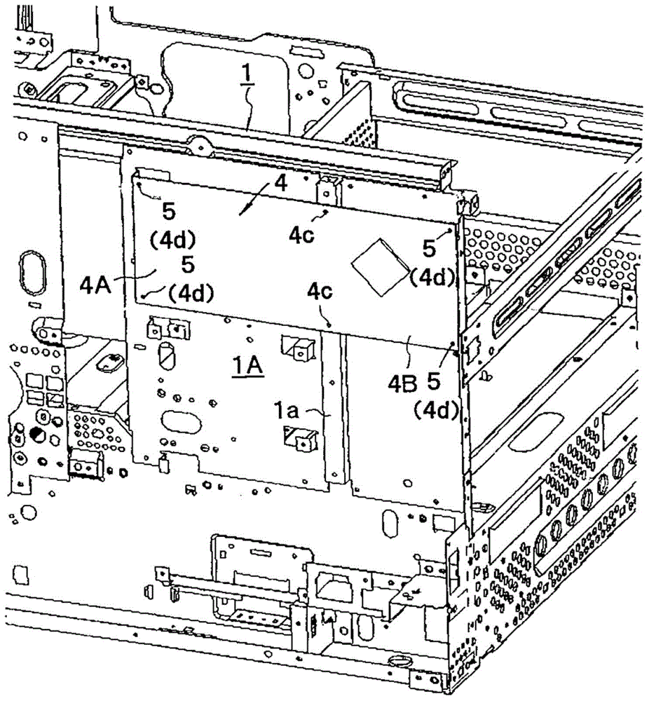
[0022] like figure 1 As shown, the main body of an image forming apparatus such as a copying machine according to the present embodiment includes a main body frame (casing) 1 made of a metal plate in a rectangular frame shape. A flat substrate mounting surface 1A is formed on one side (for example, the back) of the main body frame 1 . Further, on the substrate mounting surface 1A, a convex portion 1 a having a U-shaped cross section formed by bending a metal plate is integrally formed in the vertical direction. Protrusions 1b are integrally formed at the upper and lower portions of the upper half of the protrusion 1a. A screw hole 2 is formed in the center of each protrusion 1b.

[0023] On the left and right ends of the upper half of the substrate mounting portion 1A of the main body frame 1 divided by the convex portion 1a, L-shaped curved mounting supports 1c are formed...


PUM


Abstract

The invention provides a shield structure for an electronic apparatus. By adopting the shield structure, the number of screws and wiring harnesses is reduced; and by adopting a miniaturized shield box, the cost is prevented from rising, and noise radiation from a wiring substrate is stably reduced. The shield structure for the electronic apparatus includes a frame member and the shield box. The frame member is a conductive frame to which the wiring substrate is attached and covering a back surface of the wiring substrate. The shield box is formed on a front surface of the wiring substrate having an electronic component mounted thereon, to cover an area of a portion of the front surface. The wiring substrate includes a plurality of connecting portions formed thereon that ground the front surface and the back surface to the frame member. On a side on which the wiring substrate protrudes from the shield box, the shield box includes a shield wall member forming a wall surface substantially perpendicular to the wiring substrate. The shield wall member is grounded to at least one location of the connecting portions of the wiring substrate in the vicinity of the wall surface.

Description

technical field [0001] The present invention relates to a shielding structure of electronic equipment for shielding a wiring board mounted on the electronic equipment. Background technique [0002] Electronic equipment such as image forming devices such as copiers and printers that form images on paper by electrophotography are provided with multiple wiring boards such as drive system control boards and image processing boards. The radiated noise may cause malfunction of other electronic components. [0003] Therefore, radiation noise is shielded by accommodating and shielding a wiring board on which electronic components that generate radiation noise are mounted in a closed space of a main body frame made of a metal plate. [0004] However, accommodating wiring boards such as a drive system control board and an image processing board in a closed space of the main frame is not easy in terms of structure and cost. [0005] like Image 6 As shown in the cross-sectional view ...

Claims


Application Information

Patent Timeline
Patent Type & Authority Applications(China)
IPC IPC(8): H05K9/00
CPCH05K9/0058G03G21/1619H05K9/0037
Inventor 正木彰洋冈内庆文
Owner KYOCERA DOCUMENT SOLUTIONS INC
Why Eureka
Try Eureka