Dust removal airway

An air channel and airflow channel technology, applied in the field of pipeline design, can solve problems such as uneven flow and achieve the effect of uniform air distribution

Inactive Publication Date: 2014-06-18
周汉忠
View PDF2 Cites 8 Cited by
  • Summary
  • Abstract
  • Description
  • Claims
  • Application Information

AI Technical Summary

Problems solved by technology

[0003] The object of the present invention is to provide a dedusting air channe

Method used


Image

  • Dust removal airway

Examples


Embodiment Construction

[0008] The dust-removing air duct provided by the present invention will be further described in detail below in conjunction with the accompanying drawings.

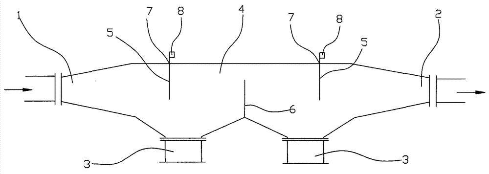
[0009] Such as figure 1 As shown, the present invention provides a dust-removing air channel, including an air channel 3, an air distribution port 1 and an exhaust port 2 located at both ends of the air channel 3, an upper baffle 7 vertically arranged above the inner wall of the air channel 3, a vertical To the lower baffle 6 and the dust outlet 3 arranged under the inner wall of the air passage 3, the dust outlet 3 is located below the upper baffle 7, the air distribution port 1 and the exhaust port 2 are tapered, and the tapered air distribution port 1 and The big ends of the exhaust ports 2 are all connected to the air flow channel 3 . Air flow channel 3 is provided with the socket 5 that matches upper baffle plate 7, and the end of upper baffle plate 7 is fixed with movable block 8, and movable block 8 is positioned...


PUM


Abstract

The invention provides a dust removal airway comprising an airflow channel, an air distributing hole, an exhaust hole, upper baffle plates, lower baffle plates and a dust discharge hole, wherein the air distributing hole and the exhaust hole are formed in the positions at two ends of the airflow channel; the upper baffle plates are vertically arranged above the inner wall of the airflow channel; the lower baffle plates are vertically arranged and the dust discharge hole is vertically formed below the inner wall of the airflow channel; the dust discharge hole is formed below the upper baffle plates; the air distribution hole and the exhaust hole are conical; the large ends of the conical air distribution hole and the exhaust hole are communicated with the airflow channel. The dust removal airway disclosed by the invention comprises a plurality of upper baffle plates and lower baffle plates which are arranged at intervals; the even zigzag dust removal airway is provided, and the air distribution hole and the exhaust hole are formed in conical shapes, so that air can be effectively and evenly distributed.

Description

technical field [0001] The invention relates to the field of pipeline design, in particular to a dust removal air duct. Background technique [0002] The present chimneys all have no dust removal device, or the dust removal device is too complicated, and the cost is too high to be practical. Therefore need to propose a kind of simple in structure badly, the dedusting device with high efficiency. Contents of the invention [0003] The object of the present invention is to provide a dedusting air channel to solve the problem of uneven flow in the above-mentioned prior art problems. [0004] The invention provides a dust-removing air channel, which comprises an air channel, an air distribution port and an exhaust port located at both ends of the air channel, an upper baffle vertically arranged above the inner wall of the air channel, and an upper baffle vertically arranged below the inner wall of the air channel. The lower baffle and the dust outlet, the dust outlet is loca...

Claims


Application Information

Patent Timeline
IPC IPC(8): B01D45/08
Inventor 周汉忠
Owner 周汉忠
Why Eureka
Try Eureka