Rolling control apparatus and rolling control method

A control device and control method technology, which is applied to the operation end and the field of feedback selection, can solve the problems of speed change, outlet side plate thickness change, speed change, etc., and achieve the effect of suppressing vibration

Active Publication Date: 2014-06-18
HITACHI LTD
View PDF8 Cites 6 Cited by
  • Summary
  • Abstract
  • Description
  • Claims
  • Application Information

AI Technical Summary

Problems solved by technology

As a problem in the case of performing constant torque control on the tension reel, the following problems can be mentioned: If the tension on the entry and exit sides of the calender fluctuates, in order to suppress it, the speed of the tension reel fluctuates, and the calender The speed of the entering side plate changes, so the thickness of the exiting side plate changes

Method used


Image

  • Rolling control apparatus and rolling control method
  • Rolling control apparatus and rolling control method
  • Rolling control apparatus and rolling control method

Examples


Embodiment Construction

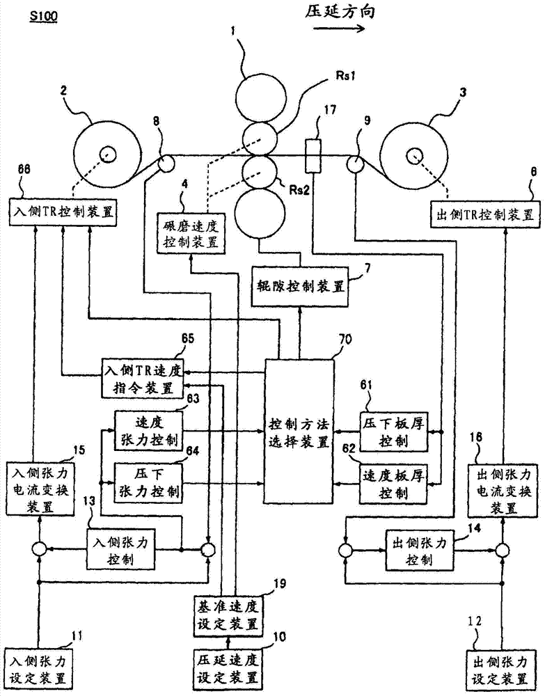
[0040] Hereinafter, the present invention will be described in detail by taking, as an example, a single-stand calender which is a typical calender using a tension roll for unwinding and winding of a material to be calendered. Figure 10 It is a figure which shows the control structure of the single stand calender S100. The rolling direction of the single-support calender S100 relative to the calender 1 (in Figure 10Indicated by the arrow in the middle), there is an entry tension reel 2 (hereinafter referred to as the entry side TR2) on the entry side of the calender 1 that releases the calendered material u, and on the exit side, there is a roll that is rolled by the calender 1. The exit side tension reel 3 (hereinafter referred to as exit side TR3) of the rolled material u.

[0041] The entry-side TR2 and the exit-side TR3 are respectively driven by electric motors, and the entry-side TR control device 5 and the exit-side TR control device 6 are respectively provided as th...


PUM


Abstract

The invention relates to an apparatus for controlling the structure that generates tensile force on a rolled material in the inlet side and outlet side of a rolling machine so as to compress the vibaration of the plate pressure on the outlet side of the rolling machine. The invention provides a rolling control apparatus, namely a rolling machine which rolls a rolled material by controlling a roller pair. The rolling apparatus is characterized by comprising a roller gap control part, which is used to control the gap between the tensile force control rollers, wherein the tensile force control rollers are inserted into the rolling machine to roll the rolled material or roll the rolled material that is discharged from the rolling machine; and a speed control part, which is used to control the conveying speed that the rolled material is inserted into the rolling machine or the rolled material is discharged out of the rolling machine according to the plate thickness of the rolled material.

Description

technical field [0001] The present invention relates to a calendering control device, a calendering control method and a calendering control program, and more specifically relates to the selection of an operating terminal and feedback of a calender having multiple operating terminals and feedbacks. Background technique [0002] In a calender that uses a tension drum for unwinding and winding of a material to be rolled, the tension drum is operated by constant torque control (constant current control). As a problem in the case of constant torque control of the tension reel, the following problems can be cited: if the tension on the entry and exit sides of the calender fluctuates, in order to suppress it, the speed of the tension reel fluctuates, and the calender The speed of the entering side plate changes, so the thickness of the exiting side plate varies. As a countermeasure, in the tension control with the speed of the tension reel as the operating end, the tension reel i...

Claims


Application Information

Patent Timeline
Patent Type & Authority Applications(China)
IPC IPC(8): B21B37/00
CPCB21B37/007B21B37/16B21B37/46B21B37/58
Inventor 服部哲
Owner HITACHI LTD
Why Eureka
Try Eureka