
Rack billet chamfering machine with four-edge chamfering function

A rack billet and chamfering machine technology, which is applied in the manufacture of tools, milling machine equipment details, metal processing, etc., can solve the problems of low processing efficiency and achieve the effect of high processing efficiency and reasonable structural design

Active Publication Date: 2014-06-18
南通众仁金属制品科技有限公司
View PDF9 Cites 3 Cited by
  • Summary
  • Abstract
  • Description
  • Claims
  • Application Information

AI Technical Summary

Problems solved by technology

[0002] The rack billet chamfering machine is a device for chamfering the edge of the rack billet. The existing rack billet chamfering machine realizes the chamfering function of one edge, and the processing efficiency is low.

Method used


Image

  • Rack billet chamfering machine with four-edge chamfering function
  • Rack billet chamfering machine with four-edge chamfering function
  • Rack billet chamfering machine with four-edge chamfering function

Examples


Embodiment Construction

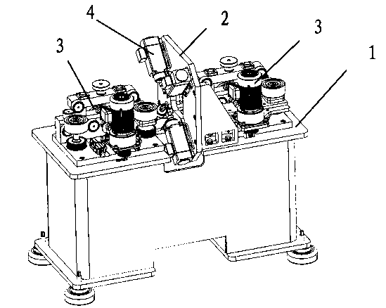
[0012] The present invention will be further described in detail below in conjunction with the accompanying drawings and examples. The following examples are explanations of the present invention and the present invention is not limited to the following examples.

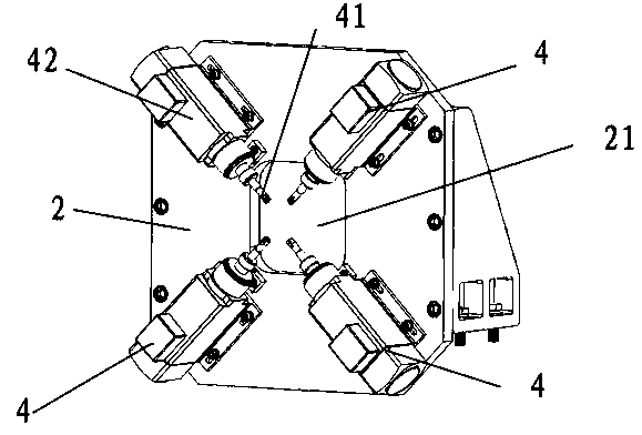
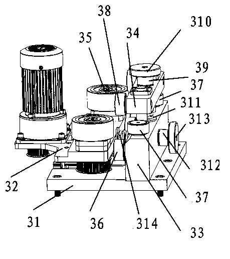
[0013] see Figure 1-Figure 3 , the rack billet chamfering machine with four-edge chamfering function in this embodiment includes a chamfering machine base 1, a chamfering machine installation base plate 2, a pair of clamping feeding devices 3 and four chamfering devices 4, the chamfering machine The installation base plate 2 is fixed on the chamfering machine base 1, and both sides of the chamfering machine installation base plate 2 are provided with clamping and feeding devices 3, and the chamfering device 4 is fixed on the chamfering machine installation base plate 2, and the chamfering device 4 includes chamfering The milling cutter 41 and the chamfering motor 42 driving the chamfering milling cutter 41, the cha...


PUM


Abstract

The invention discloses a rack billet chamfering machine with a four-edge chamfering function. The rack billet chamfering machine with the four-edge chamfering function comprises a chamfering machine base, a chamfering machine installation base plate, a pair of clamping and feeding devices and four chamfering devices; the chamfering machine installation base plate is fixed on the chamfering machine base; the clamping and feeding devices are arranged at two sides of the chamfering machine installation base plate; the chamfering devices are fixed on the chamfering machine installation base plate, and each chamfering device comprises a chamfering milling cutter and a chamfering motor for driving the chamfering milling cutter; the chamfering machine installation base plate is provided with a material passing hole through which rack billets can pass; the four chamfering devices are distributed around the material passing hole; and the chamfering milling cutters of the four chamfering devices respectively correspond to four edges of each rack billet. The rack billet chamfering machine with the four-edge chamfering function, which is provided by the invention, is reasonable in structure design; the four chamfering devices can chamfer four edges of each rack billet synchronously, so the processing efficiency is high; the distance between a driving feeding wheel and a driven feeding wheel can be regulated, so that the compression force can be regulated correspondingly according to rack billets with different sizes.

Description

technical field [0001] The invention relates to a rack billet chamfering machine with four-edge chamfering function. Background technique [0002] The rack billet chamfering machine is a device for chamfering the edge of the rack billet. The existing rack billet chamfering machine realizes the chamfering function of one edge by single processing, and the processing efficiency is low. Contents of the invention [0003] The purpose of the present invention is to overcome the above-mentioned deficiencies in the prior art, and provide a rack billet chamfering machine with a four-edge chamfering function that has a reasonable structural design and can chamfer the four edges of the rack billet at one time. . [0004] The technical solution adopted by the present invention to solve the above problems is: [0005] The rack billet chamfering machine with four-edge chamfering function is characterized in that it includes a chamfering machine base, a chamfering machine installation...

Claims


Application Information

Patent Timeline
IPC IPC(8): B23C3/12B23Q7/05
Inventor 谭广高尔荣
Owner 南通众仁金属制品科技有限公司
Features
  • Generate Ideas
  • Intellectual Property
  • Life Sciences
  • Materials
  • Tech Scout
  • Unparalleled Data Quality
  • Higher Quality Content
  • 60% Fewer Hallucinations
Learn More