Fixture for supporting seized main bolts of pressure container
A technology for supporting pressure and main bolts, applied in the direction of manufacturing tools, workpiece clamping devices, etc., can solve problems such as easy dumping, personnel and equipment damage, and achieve the effect of avoiding dumping accidents and protecting personnel.
- Summary
- Abstract
- Description
- Claims
- Application Information
AI Technical Summary
Problems solved by technology
Method used
Image
Examples
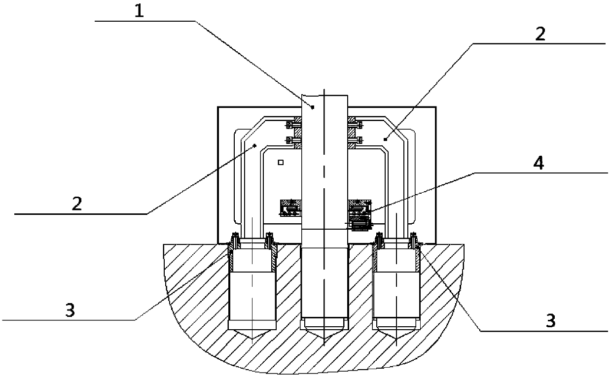
Embodiment 1
[0024] For the working condition (1) the bolts on the adjacent sides of the main bolt 1 to be cut to death have not been killed, and have been successfully removed.
[0025] Such as figure 1 As shown, the left and right clamps include: screw sleeve 3 and inverted Shaped fixture body 2. The screw sleeve 3 is a cylinder with a closed upper end, and its side wall is provided with threads, and the screw sleeve 3 is screwed into the screw holes on both sides of the adjacent main bolt for positioning; the inverted Shaped clamp body 2, one end of which is fixed on the part where the main bolt protrudes from the flange surface of the pressure vessel through a fixing component such as a screw, and the other end is fixed on the part that is screwed into the screw holes on both adjacent sides through a fixing component such as a screw or a flange. On the screw sleeve 3. upside down The contact surface between the clamp body 2 and the main bolt 1 to be cut and killed is an arc-shap...
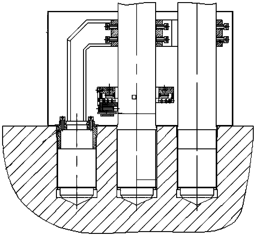
Embodiment 2
[0027] For the working condition (2), there are dead bolts adjacent to the bolts on both sides of the main bolt 1 to be cut and dead, and the adjacent dead bolts have not been cut.
[0028] Such as figure 2 As shown on the right side, on the side of the dead bolt adjacent to the dead main bolt 1 to be cut, the following type of fixture is used: the fixture consists of two components: component one is connected by two arc-shaped clips facing back and The second component is an independent arc-shaped clamp. An arc-shaped clamp of component one is placed on the side wall of the main bolt 1 to be cut and killed, and is fastened with the clamp on the other side of the main bolt 1 to be cut and killed by screws. The other arc-shaped clamp of component one The hoop is placed on the side wall of the dead bolt adjacent to the main bolt 1 to be cut, and it is fastened with the component two on the other side of the dead bolt by screws.
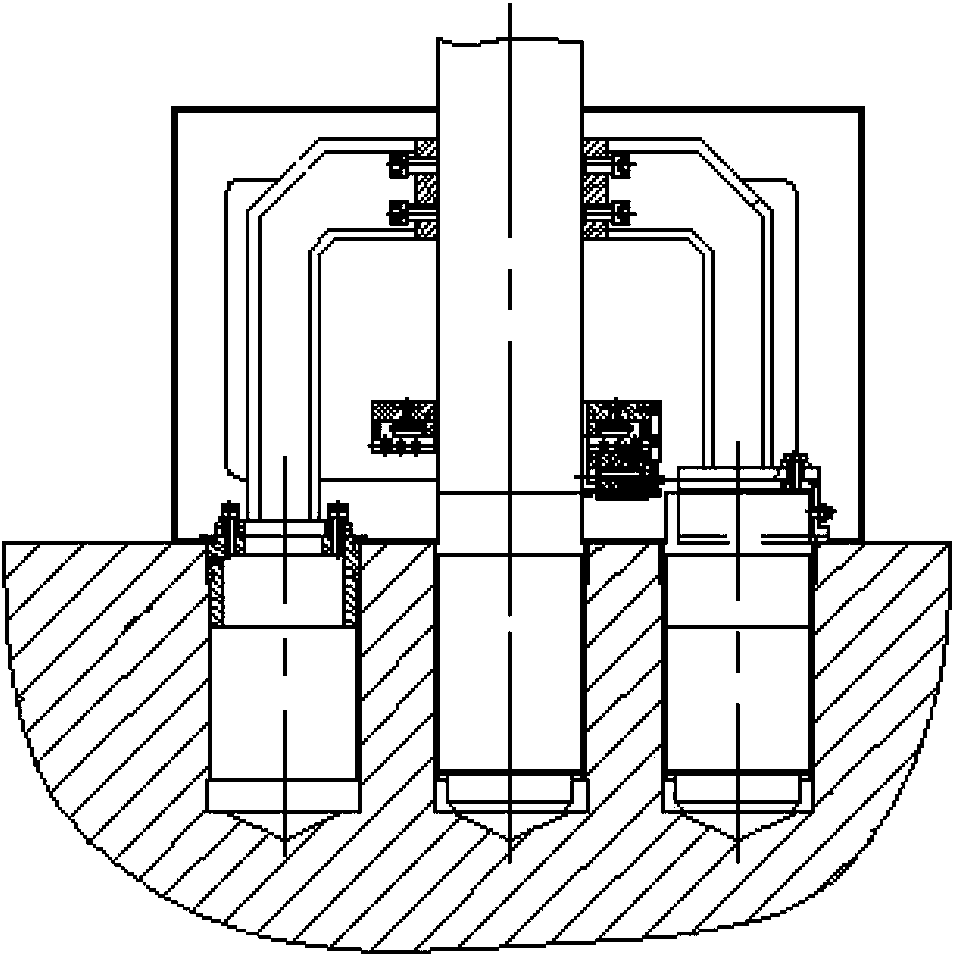
Embodiment 3
[0030] For the working condition (3), there are dead bolts adjacent to the bolts on both sides of the main bolt 1 to be cut and dead, and the adjacent dead bolts have been cut off, leaving only a short part protruding from the flange surface of the pressure vessel.
[0031] Such as image 3 As shown on the right, on the side where there is a dead bolt adjacent to the dead main bolt 1 to be cut, the following types of clamps are used: round sleeve and inverted Shaped fixture body 2. The circular sleeve is a cylinder with a sealed upper end and an open lower end, which is placed over the cut-off bolt on this side for positioning; the inverted Shaped fixture body 2, one end of which is fixed on the part where the main bolt is stuck and protrudes from the flange surface of the pressure vessel through a fixing component such as a screw, and the other end is fixed on the round sleeve. upside down The contact surface between the clamp body 2 and the main bolt 1 to be cut and ki...
PUM
 Abstract
Description
Claims
Application Information
 - R&D
- Intellectual Property
- Life Sciences
- Materials
- Tech Scout
- Unparalleled Data Quality
- Higher Quality Content
- 60% Fewer Hallucinations
Browse by: Latest US Patents, China's latest patents, Technical Efficacy Thesaurus, Application Domain, Technology Topic, Popular Technical Reports.
© 2025 PatSnap. All rights reserved.Legal|Privacy policy|Modern Slavery Act Transparency Statement|Sitemap|About US| Contact US: help@patsnap.com


