
Clamps for Vacuum Piping

A fixture and vacuum technology, applied in the direction of manufacturing tools, workpiece clamping devices, pipes/pipe joints/fittings, etc., can solve problems such as loosening of fixtures, release of airtight connection status of vacuum piping, and loosening of fastening nuts. achieve a firm bond

Active Publication Date: 2016-03-30
MI
View PDF8 Cites 0 Cited by
  • Summary
  • Abstract
  • Description
  • Claims
  • Application Information

AI Technical Summary

Problems solved by technology

[0006] However, this conventional vacuum piping jig has the problem that the tightening state of the fastening nut is gradually loosened as the vacuum piping continues to vibrate, causing the jig to loosen, and the airtight connection state of the vacuum piping is released.

Method used


Image

  • Clamps for Vacuum Piping
  • Clamps for Vacuum Piping
  • Clamps for Vacuum Piping

Examples


Embodiment Construction

[0035] Below, with reference to the accompanying drawings, the content of the present invention will be described in detail through embodiments. The following embodiments are merely illustrative, and it is a matter of course that the scope of rights of the present invention is not limited thereto.

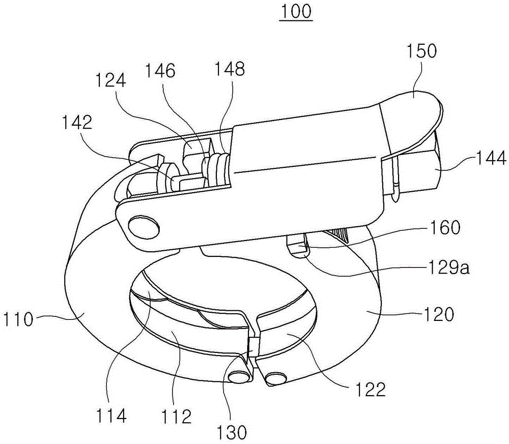
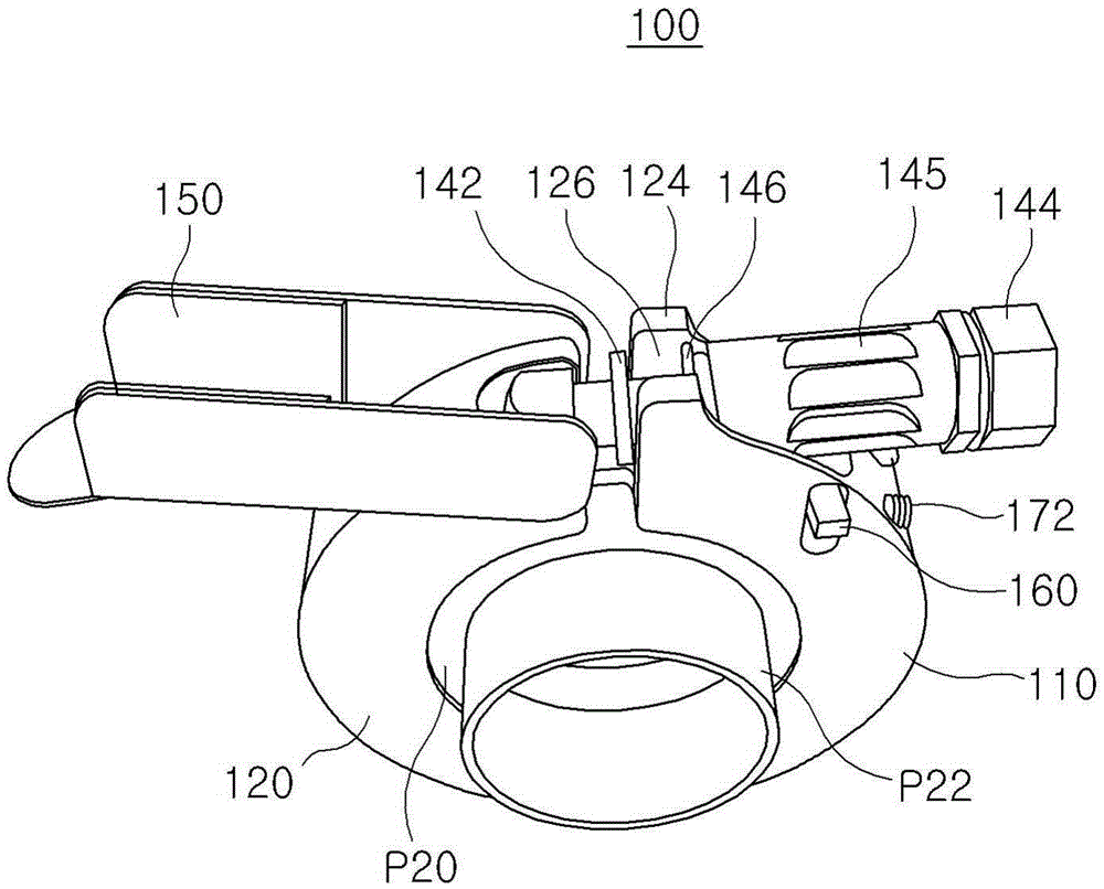
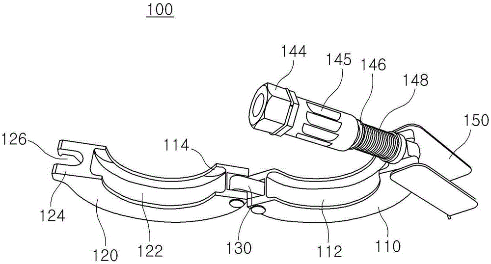
[0036] refer to Figure 1 to Figure 8 , the present invention is a jig 100 for vacuum piping, which can separate the first flange P12 of the first piping P10 and the second flange P22 of the second piping P20 in a state of being in contact with each other via the central ring CR. be fixed. The center ring CR has a portion formed of a metal material and a portion formed of a rubber material outside the portion. The above-mentioned portion made of a rubber material is used to ensure airtightness at the contact surface between the first flange P12 and the second flange P22.

[0037] The jig 100 for vacuum piping includes a first jig 110 and a second jig 120 . The first insertion g...


PUM


Abstract

The present invention relates to an improved clamp for vacuum lines that comprises vacuum lines for maintaining a vacuum state in the main equipment in a semiconductor manufacturing process and stably maintains the connection state of the vacuum lines in an airtight state without loosening due to the vibration of the vacuum lines. The clamp for vacuum lines is arranged between the center rings, separates a first flange of a first line and a second flange of a second line in a contact state, and includes a first semicircular clamp formed in the first insertion hole of the first and the second flange as an inner diameter. A second semicircular clamp is formed in the second insertion hole of the first and the second flange as an inner diameter. A connection link is hinge-combined with both sides to rotate in regard to the free end of the first and second clamps. One end of a locking member is hinge-combined with the first clamp and the other end is detachable from the second clamp. A fixing protrusion having a fixing groove is formed in the free end of the second clamp. At least one sub fixing member moves through an entrance hole formed on the outer surface of the first and the second clamp.

Description

technical field [0001] The present invention relates to a jig for vacuum piping, and more specifically, to an improved jig for vacuum piping provided with a plurality of vacuum piping lines for maintaining a vacuum state in main equipment during a semiconductor manufacturing process. The wires vibrate continuously, and will not loosen due to this vibration, and can maintain an airtight state, and at the same time, can maintain the connection state of the vacuum piping firmly. Background technique [0002] Generally, a semiconductor manufacturing process is roughly composed of a pre-process (manufacturing process) and a post-process (packaging process). In the previous process, thin films are evaporated on wafers (Wafer) in various processing chambers, and the evaporated thin films are selectively etched, and specific patterns are processed by repeatedly performing these processes, thereby manufacturing semiconductor chips ( Chip). In addition, in the subsequent process, af...

Claims


Application Information

Patent Timeline
Patent Type & Authority Patents(China)
IPC IPC(8): B25B11/00
CPCB25B11/00F16B39/02F16L21/06F16L21/08H01L21/67017
Inventor 金基南
Owner MI
Learn More