
Material transfer device

A transfer device and material technology, which is applied in metal processing and other directions, can solve the problem that the shearing machine cannot be aligned with the material, and achieve the effect of convenient processing

Active Publication Date: 2014-06-18
江苏君墨智能装备有限公司
View PDF5 Cites 1 Cited by
  • Summary
  • Abstract
  • Description
  • Claims
  • Application Information

AI Technical Summary

Problems solved by technology

However, due to the mechanical arm in the forming machine, the shearing machine cannot be aligned with the material

Method used


Image

  • Material transfer device
  • Material transfer device
  • Material transfer device

Examples


Embodiment Construction

[0014] The material transfer device in the present invention will be described in further detail below in conjunction with the accompanying drawings.

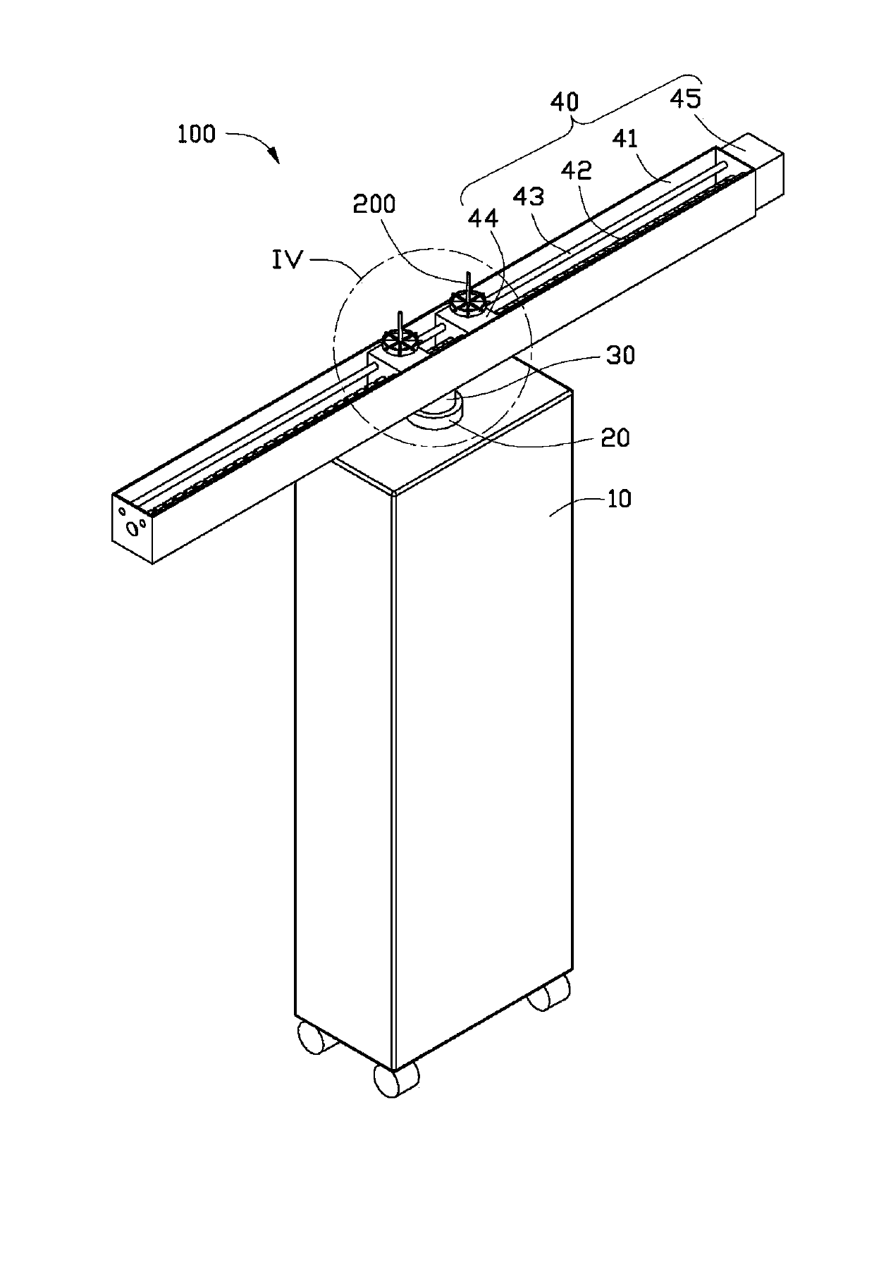
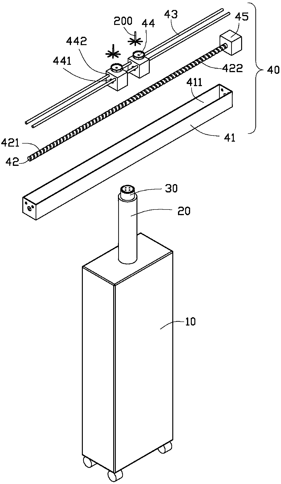
[0015] Please refer to figure 1 and figure 2 , in a preferred embodiment of the present invention, the material transfer device 100 is used to transfer the material produced by the forming machine to the shearing machine for shearing. The material transfer device 100 includes a base 10 , a support rod 20 , a rotating part 30 and a transfer mechanism 40 . The transfer mechanism 40 is rotatably connected to the top of the base 10 through the support rod 20 and the rotating part 30, and rotates under the drive of the rotating part 30, thereby transporting the materials placed on the transfer mechanism 40 to the shear The location of the cutting machine.

[0016] The base 10 is a cuboid structure, and the support rod 20 is telescopically arranged on the top of the base 10, which is pushed by a driving mechanism (such as a cylin...


PUM


Abstract

The invention provides a material transfer device comprising abase, a rotary part and a transfer mechanism, wherein the rotary part is arranged on the top of the base, the transfer mechanism comprises a rotary frame, material carrying table arranged on the rotary frame and used for bearing materials, and a driving device, the rotary frame is rotatably connected to the base by virtue of the rotary part, the material carrying table is driven by the driving device and thus capable of sliding relatively to the rotary frame. The material transfer device is capable of transferring materials molded by a molding machine to a position to which a mechanical arm of a shearing machine can be aligned, and therefore, the shearing machine is capable of processing the materials conveniently.

Description

technical field [0001] The invention relates to a material transfer device. Background technique [0002] In order to save the cost of the molding machine, the mold of some molding machines is designed to mold two materials at the same time in one mold, and the two materials need two shears to cut. However, due to the manipulator in the forming machine, the shearing machine cannot be aligned with the material. Contents of the invention [0003] In view of this, it is necessary to provide a material transfer device, the material transfer device includes: a base, a rotating part and a transfer mechanism, wherein the rotating part is arranged on the top of the base, the transfer mechanism includes a rotating frame, is arranged on the rotating frame The material carrying table and the driving device for carrying materials on the top, the rotating frame is rotatably connected to the base through the rotating part, and the material carrying table is driven by the driving device...

Claims


Application Information

Patent Timeline
IPC IPC(8): B26D7/06
Inventor 郭明龙
Owner 江苏君墨智能装备有限公司
Learn More