
Control method of printing machine and printing machine

A control method and printer technology, applied in the control of printers and the field of printers, can solve the problems of uneven printing density and ineffectiveness of printing energy compensation, and achieve the effects of solving uneven pressure and improving printing density.

Active Publication Date: 2014-06-18
SHANDONG NEW BEIYANG INFORMATION TECH CO LTD
View PDF6 Cites 1 Cited by
  • Summary
  • Abstract
  • Description
  • Claims
  • Application Information

AI Technical Summary

Problems solved by technology

[0006] The main purpose of the present invention is to provide a printer control method and printer to solve the problem that the printing energy compensation in the related art cannot effectively solve the uneven printing density of each printing point caused by the uneven pressure between the printing head and the printing rubber roller method problem

Method used


Image

  • Control method of printing machine and printing machine
  • Control method of printing machine and printing machine
  • Control method of printing machine and printing machine

Examples


Embodiment Construction

[0028] It should be noted that the embodiments in the present application and the features of the embodiments may be combined with each other in the case of no conflict. The present invention will be described in detail below with reference to the accompanying drawings and in conjunction with the embodiments.

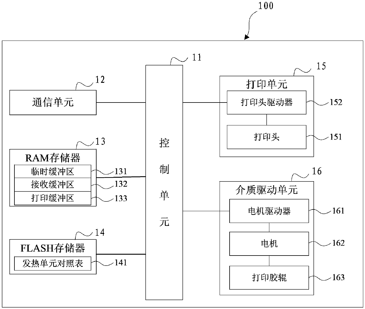
[0029] figure 2 It is a schematic diagram of the composition of the printer according to the first embodiment of the present invention. As shown in the figure, the printer 100 includes a control unit 11 , a communication unit 12 , a RAM memory 13 , a FLASH memory 14 , a printing unit 15 and a media drive unit 16 . in,

[0030] The control unit 11 is used to control each module to perform work, for example, the control unit 11 controls the communication unit 12 to perform data transmission between the printer 100 and a print request device (such as a computer or a network device); The data is processed to generate dot matrix data to be sent to the print head of the p...


PUM


Abstract

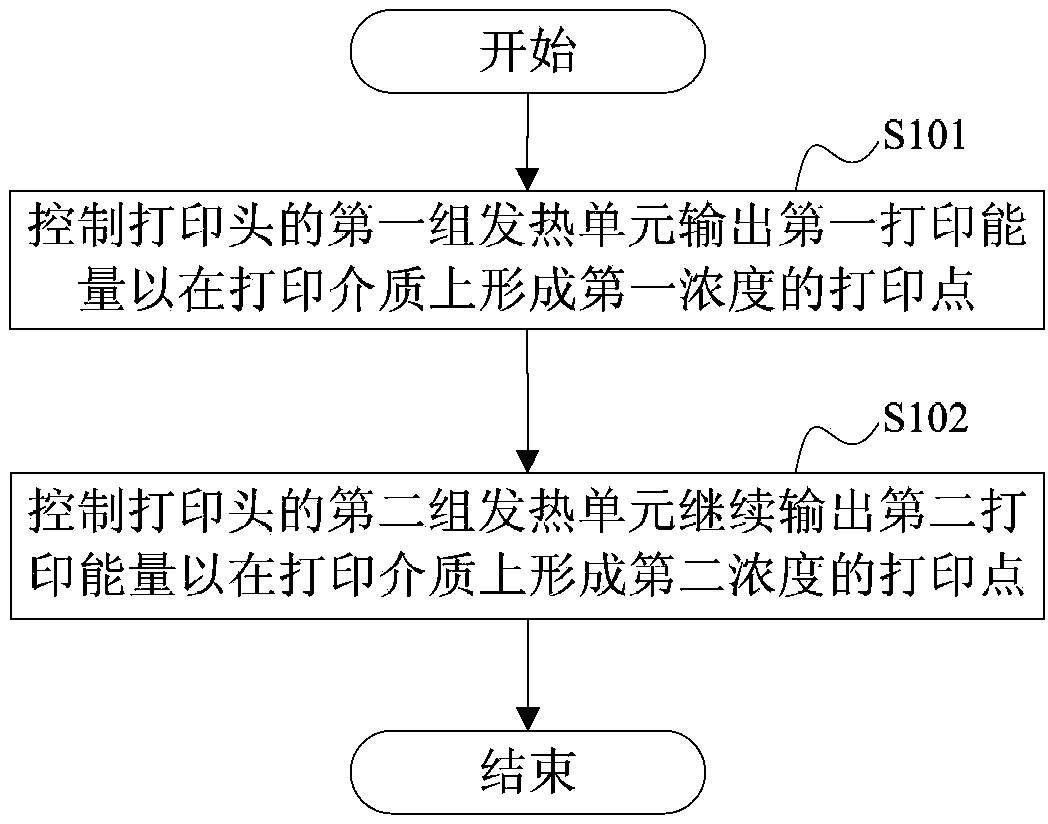
The invention discloses a control method of a printing machine and the printing machine, wherein the control method of the printing machine comprises the following steps that a first group of heating units of a printing head are controlled to output first printing energy for forming printing points at the first concentration on a printing medium; a second group of heating units of the printing head are controlled for continuously outputting second printing energy for forming printing points at second concentration on the printing medium, wherein the second group of heating units consist of heating units requiring printing energy compensation in the first group of heating units. Through the control method and the printing machine provided by the invention, the printing concentration of the heating units requiring the printing energy compensation on the corresponding printing points is improved, and the problem of nonuniform printing concentration of each printing point caused by nonuniform pressure between the printing head and a printing rubber roller can be effectively solved.

Description

technical field [0001] The present invention relates to the field of printing, in particular, to a control method of a printer and a printer. Background technique [0002] At present, the application range of thermal printers is more and more extensive. The printing mechanism of the thermal printer includes a thermal printing head and a printing rubber roller. The thermal printing head and the printing rubber roller are arranged tangentially, and the printing consumables pass between them. Multiple heating units, when the printer performs a printing task, the heating unit generates energy (referred to as printing energy) by controlled heating, and the printing energy is transferred to the printing consumables in contact with the thermal print head. Among them, in a thermal printer, the printing consumables are It refers to the thermal printing medium. The printing energy causes the thermal layer on the surface of the thermal printing medium to chemically change, so as to de...

Claims


Application Information

Patent Timeline
Patent Type & Authority Applications(China)
IPC IPC(8): B41J29/38B41J2/315
CPCB41J2/315B41J2/36B41J2/365B41J2/362B41J2/37
Inventor 丁进峰王国凯胡广东王鑫
Owner SHANDONG NEW BEIYANG INFORMATION TECH CO LTD
Learn More