Pneumatic stopper

A car stopper and pneumatic technology, applied in the direction of mandatory railway car stopper, railway car body parts, transportation and packaging, etc., can solve the problems of high cost, resignation of operators, and high requirements for the operating environment, and achieve simple structure and avoid Potential safety hazards and the effect of enhancing safety and reliability

Inactive Publication Date: 2014-06-18
安阳县安达机械有限责任公司
View PDF0 Cites 0 Cited by
  • Summary
  • Abstract
  • Description
  • Claims
  • Application Information

AI Technical Summary

Problems solved by technology

At present, manual car stoppers are widely used, with one slope and three gears, multiple hinge points, complex mechanisms, high cost, and high requirements fo

Method used


Image

  • Pneumatic stopper
  • Pneumatic stopper

Examples


Embodiment Construction

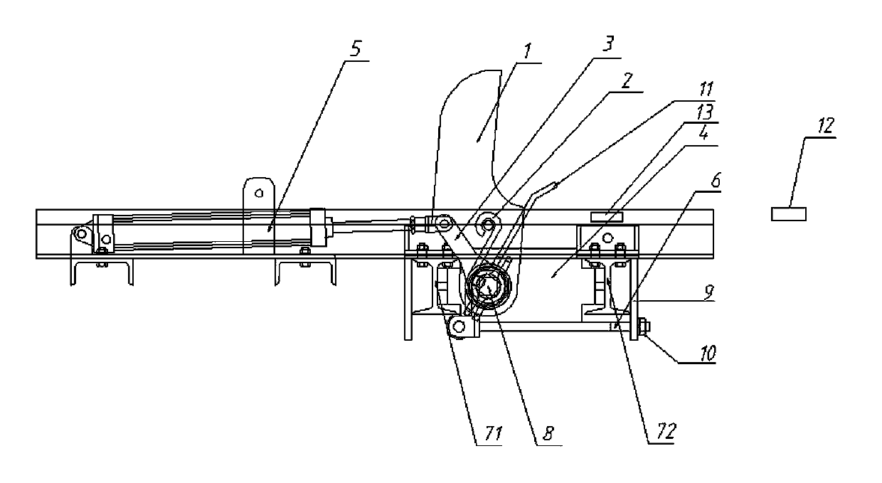
[0013] Such as figure 1 The pneumatic car arrester shown includes knife block 1, torsion spring 2, force handle 3, cylinder 5, axle frame 4, shaft 8, left limit plate 71, right limit plate 72 and pull rod 6, and axle frame 4 is fixed On the two limiting plates, the far end of the shaft 8 passes through the torsion spring 2 and is hinged on the shaft frame 4, the knife stopper 1 is fixed on the shaft 8 and connected with the upper end of the torsion spring 2, and the lower end of the torsion spring 2 is fixed on the pull rod 6 , force the 3 lower ends to be fixed on the proximal end of the shaft 8, and force the 3 upper ends to be hinged with the cylinder 5; the right side of the right limit plate 72 stretches out a steel plate 9 downwards, the left end of the pull rod 6 is fixed on the lower end of the torsion spring 2, and the right end of the pull rod 6 It passes through the steel plate 9 and is provided with an adjusting nut 10 .

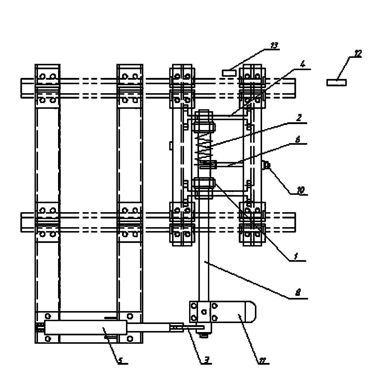
[0014] Such as figure 2 The pneumatic c...


PUM


Abstract

The invention discloses a pneumatic stopper which comprises a tool barrier, a torsion spring, a force handle, a cylinder, a shaft bracket, a shaft, a limit plate and a pull rod. The shaft bracket is fixed onto the limit plate, a far end of the shaft penetrates the torsion spring and is hinged onto the shaft bracket, the tool barrier is fixed onto the shaft and connected with the upper end of the torsion spring, the lower end of the torsion spring is fixed onto the pull rod, the lower end of the force handle is fixed to a near end of the shaft, and the upper end of the force handle is hinged to the cylinder. The pneumatic stopper is simple in structure, safe and reliable, can be manually and remotely controlled, and realizes centralized automated management.

Description

technical field [0001] The invention relates to a vehicle blocking device installed at a slope change point and capable of driving in one direction. Background technique [0002] The car arrester is commonly used in the production process of coal mines in my country to prevent the mine car from running automatically or out of control. It can stop the mine car from running in time to prevent accidents. At present, manual car stoppers are widely used, with one slope and three gears, multiple hinge points, complex mechanisms, high cost, and high requirements for the operating environment. In actual operation, it is easy to have illegal operations such as operator resignation, which cannot be realized. remote control. Contents of the invention [0003] The object of the present invention is to overcome the above disadvantages and provide a pneumatic car arrester, which has a simple structure, is safe and reliable, can be remotely controlled, and realizes centralized automatic...

Claims


Application Information

Patent Timeline
IPC IPC(8): B61K7/16
Inventor 王文政
Owner 安阳县安达机械有限责任公司
Why Eureka
Try Eureka