A vehicle simulator

A driver and vehicle technology, applied in the field of vehicles and vehicle simulation drivers, can solve problems such as high maintenance costs, unsuitable for simple and cheap test principles, complex system control, etc., and achieve the effect of facilitating steering stability

Inactive Publication Date: 2016-03-30
KUNMING UNIV OF SCI & TECH
View PDF5 Cites 0 Cited by
  • Summary
  • Abstract
  • Description
  • Claims
  • Application Information

AI Technical Summary

Problems solved by technology

Compared with hydraulic and electric multi-degree-of-freedom platforms, they have good mechanical properties, strong bearing capacity, low noise, and are close to the structure of real vehicles, but the construction cost is high, the maintenance cost is high, and the system control is relatively complicated.
Hydraulic and electric costs are too high for small tests, not suitable for simple and cheap test principles

Method used


Image

  • A vehicle simulator
  • A vehicle simulator
  • A vehicle simulator

Examples


Embodiment approach 1

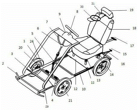
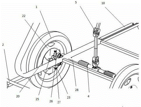
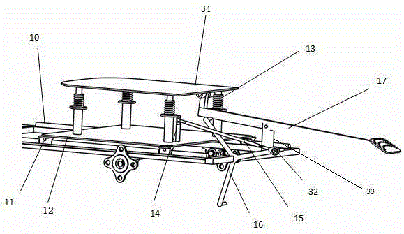
[0027] Embodiment 1: if Figures 1 to 6As shown, the driver of this embodiment includes a front wheel steering system, and also includes a seat system with vibration and motion functions. The seat system with vibration and motion functions includes an elastic device and a bump pedal 17. The elastic device is on the upper A spring push column 14 is installed between the bracket 34 and the lower bracket, the seat is installed on the upper bracket 34, the up and down bump pedal 17 is hinged on the frame through the rear column 33, and one end of the up and down bump pedal 17 is fixed on the upper bracket through a bearing The lower surface of 34; the seat system with vibration and motion function also includes a sliding rail device and a triangular turning plate 16. The sliding rail device is a seat through the slider 11 to install the lower bracket 12 on the sliding rail 10 of the frame, and the triangular rotation The disc 16 is composed of three sides that meet at one point an...

Embodiment approach 2

[0028] Embodiment 2: as Figures 1 to 6 As shown, the driver of this embodiment includes a front wheel steering system, and also includes a seat system with vibration and motion functions. The seat system with vibration and motion functions includes an elastic device and a bump pedal 17. The elastic device is on the upper A spring push column 14 is installed between the bracket 34 and the lower bracket, the seat is installed on the upper bracket 34, the up and down bump pedal 17 is hinged on the frame through the rear column 33, and one end of the up and down bump pedal 17 is fixed on the upper bracket through a bearing The lower surface of 34; the seat system with vibration and motion function also includes a sliding rail device and a triangular turning plate 16. The sliding rail device is a seat through the slider 11 to install the lower bracket 12 on the sliding rail 10 of the frame, and the triangular rotation The disc 16 is composed of three sides that meet at one point a...

Embodiment approach 3

[0029] The third embodiment is as Figures 1 to 6 As shown, the driver of this embodiment includes a front wheel steering system, and also includes a seat system with vibration and motion functions. The seat system with vibration and motion functions includes an elastic device and a bump pedal 17. The elastic device is on the upper A spring push column 14 is installed between the bracket 34 and the lower bracket, the seat is installed on the upper bracket 34, the up and down bump pedal 17 is hinged on the frame through the rear column 33, and one end of the up and down bump pedal 17 is fixed on the upper bracket through a bearing The lower surface of 34; the seat system with vibration and motion function also includes a sliding rail device and a triangular turning plate 16. The sliding rail device is a seat through the slider 11 to install the lower bracket 12 on the sliding rail 10 of the frame, and the triangular rotation The disc 16 is composed of three sides that meet at o...


PUM


Abstract

The invention relates to a vehicle driving simulator, and belongs to the field of carrying tool technologies. The vehicle driving simulator also comprises a seat system with vibration and motion functions, wherein the seat system with the vibration and motion functions comprises an elastic device and a longitudinal bumping pedal; the elastic device is a pushing vertical column with a spring, which is mounted between an upper bracket and a lower bracket; a seat is mounted on the upper bracket; the longitudinal bumping pedal is hinged to a frame through a rear vertical column; one end of the longitudinal bumping pedal is fixed on the lower surface of the upper bracket through a bearing; the seat system with the vibration and motion functions also comprises a sliding rail device and a triangular rotating disk; according to the sliding rail device, the lower bracket is arranged on a sliding rail of the frame by the seat through a sliding block; the triangular rotating disk consists of three edges which are intersected at a point and are mutually angled by 120 degrees, is arranged on the frame and is kept rotating; one end of the triangular rotating disk is connected with one end of a pushing pull rod through a centering bearing; the other end of the pushing pull rod is hinged to the pushing vertical column.

Description

technical field [0001] The invention relates to a vehicle simulation driver, which belongs to the technical field of vehicles. Background technique [0002] With the development and application of the electromagnetic induction type anti-collision safety helmet strap technology, in order to facilitate the experiment and test data, a low-cost vehicle simulator driver that can simulate the front and rear vibration, up-and-down bumps, steering braking and linear acceleration of the vehicle is required. The present invention It provides a better experimental platform for the technology of electromagnetic induction anti-collision safety helmet belt. Compared with the hydraulic and electric multi-degree-of-freedom platform, the mechanical properties are better, the bearing capacity is stronger, the noise is lower, and the structure is close to the real vehicle, but the engineering cost is high, the maintenance cost is high, and the system control is more complicated. Hydraulic and...

Claims


Application Information

Patent Timeline
Patent Type & Authority Patents(China)
IPC IPC(8): B62D63/02
Inventor 康瑞赵成俊杨飞杨培斌师鼎坤陈厚真杨昌瑶闫寒程皓王春荣陈蜀乔李耀平杨修建高晋张昆
Owner KUNMING UNIV OF SCI & TECH
Why Eureka
Try Eureka