Alkali soaking equipment for leather processing
A technology of leather and alkali dipping, which is applied in leather/skin/leather/rawhide chemical treatment equipment, small raw hide/large raw hide/leather/fur treatment, application, etc. Eliminate uncleanness and other problems to achieve the effect of uniform alkali dipping, simple mechanism and easy operation
- Summary
- Abstract
- Description
- Claims
- Application Information
AI Technical Summary
Problems solved by technology
Method used
Image
Examples
Embodiment 1
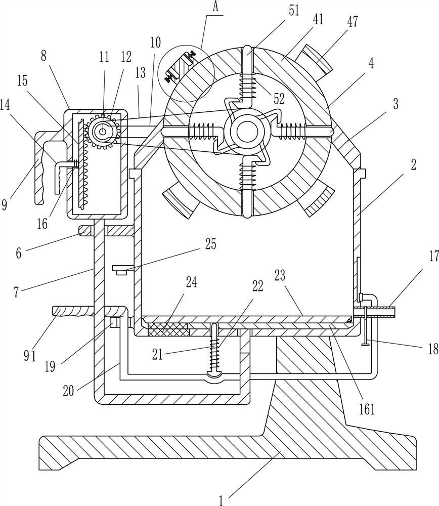
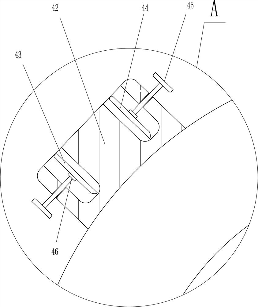
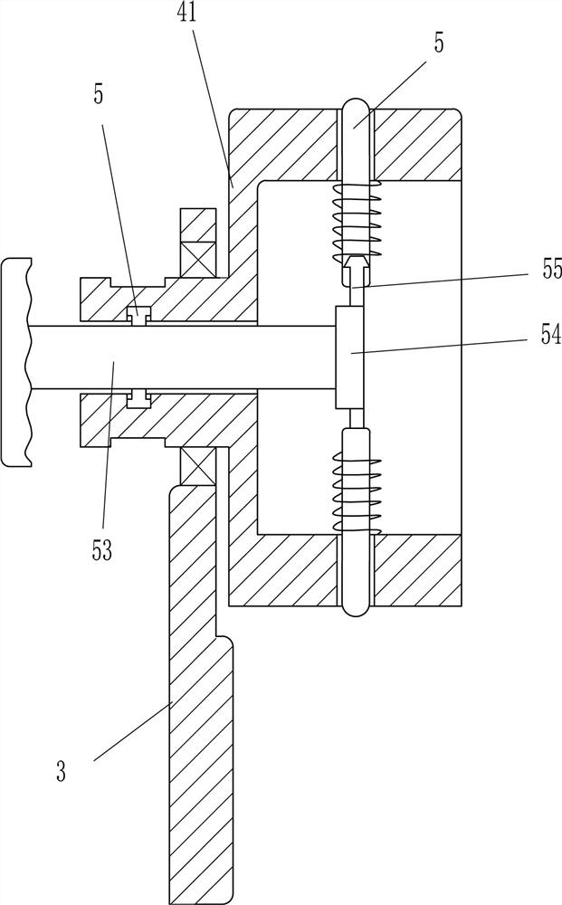
[0017] like Figure 1-3 As shown, an alkali soaking equipment for leather processing includes a base 1, a box body 2, a bracket 3, a rotary clamp 4, an ejection mechanism 5, a guide sleeve 6, a U-shaped rod 7, a square frame 8, and a handle 9 , mounting frame 10, rotating shaft 11, gear 12, transmission mechanism 13, handle 14, rack 15, second elastic member 16, movable plate 161, discharge port 17 and valve 18, the top of base 1 is provided with box body 2, The top of the box body 2 is symmetrically provided with brackets 3 by means of bolt connection, and a rotary clamp 4 for fixing the leather is provided between the two brackets 3, and a top for tightening the leather is provided on the rotary clamp 4. Out of the mechanism 5, a guide sleeve 6 is arranged on the side wall of the box body 2, a U-shaped rod 7 is movable inside the guide sleeve 6, a square frame 8 is arranged on the top of the U-shaped rod 7, and a No. 1 handle 9 is arranged on the left side of the square fram...
Embodiment 2
[0022] like figure 1 As shown, on the basis of Embodiment 1, it also includes a guide sleeve 19, a U-shaped push rod 20, a lifting rod 21, a third elastic member 22, an elastic shielding plate 23 and a screen 24, and the lower part of the left side of the box body 2 is set There is a guide sleeve 19, a U-shaped ejector rod 20 is movable in the guide sleeve 19, a No. 2 handle 91 is arranged on the top of the U-shaped ejector rod 20, an elastic shielding plate 23 is rotatably arranged on the movable plate 161, and the left side of the bottom of the box body 2 The side and the movable plate 161 vertical direction are all provided with through holes, and the lifting rod 21 is movable in the through hole on the left side of the bottom of the casing 2, and the third elastic member 22 is arranged between the lifting rod 21 and the bottom of the casing 2. The third elastic member 22 is a compression spring, the bottom of the elevating rod 21 is in contact with the U-shaped push rod 20...
PUM
 Abstract
Description
Claims
Application Information
 - R&D
- Intellectual Property
- Life Sciences
- Materials
- Tech Scout
- Unparalleled Data Quality
- Higher Quality Content
- 60% Fewer Hallucinations
Browse by: Latest US Patents, China's latest patents, Technical Efficacy Thesaurus, Application Domain, Technology Topic, Popular Technical Reports.
© 2025 PatSnap. All rights reserved.Legal|Privacy policy|Modern Slavery Act Transparency Statement|Sitemap|About US| Contact US: help@patsnap.com


