Four-shaft type flight device body assembly

A flying device and airframe technology, applied in the field of agricultural aircraft, can solve problems such as insecure performance, poor structural strength, and influence on layout, and achieve the effects of easy processing and production, reduced production costs, and reduced height and size

Inactive Publication Date: 2014-06-18
CHONGQING KINGTEC AVIATION IND
View PDF10 Cites 10 Cited by
  • Summary
  • Abstract
  • Description
  • Claims
  • Application Information

AI Technical Summary

Problems solved by technology

During use, the top cover is not only heavy and easily damaged; it is also extremely inconvenient to open and close, which is not only cumbersome to operate, but also time-consuming and labor-intensive, which greatly affects the convenience of use
However, the existing electronic governor is arranged in the equipment cabin, which not only greatly occupies the space in the equipment cabin, but also affects the arrangement of other components in the equipment cabin; it is also extremely inconvenient to disassemble and assemble, the heat dissipation performance is not good, and the use performance is not guaranteed.
In addition, the weight and volume of the fuselage of the existing agricultural unmanned aerial vehicles are large, the structural strength is poor, easy to damage, and processing is difficult
In addition, the medicine box containing the liquid medicine is generally installed under the fuselage, and the medicine box needs to be manufactured separately. The processing is difficult to assemble and the production cost is high, which will increase the height of the entire aircraft; when there is less liquid medicine in the medicine box, Affected by the working vibration of the aircraft, the liquid medicine will sway, which will affect the balance of the aircraft and reduce the effect of spraying the liquid medicine

Method used


Image

  • Four-shaft type flight device body assembly
  • Four-shaft type flight device body assembly
  • Four-shaft type flight device body assembly

Examples


Embodiment Construction

[0024] Below in conjunction with accompanying drawing and embodiment the present invention will be further described:

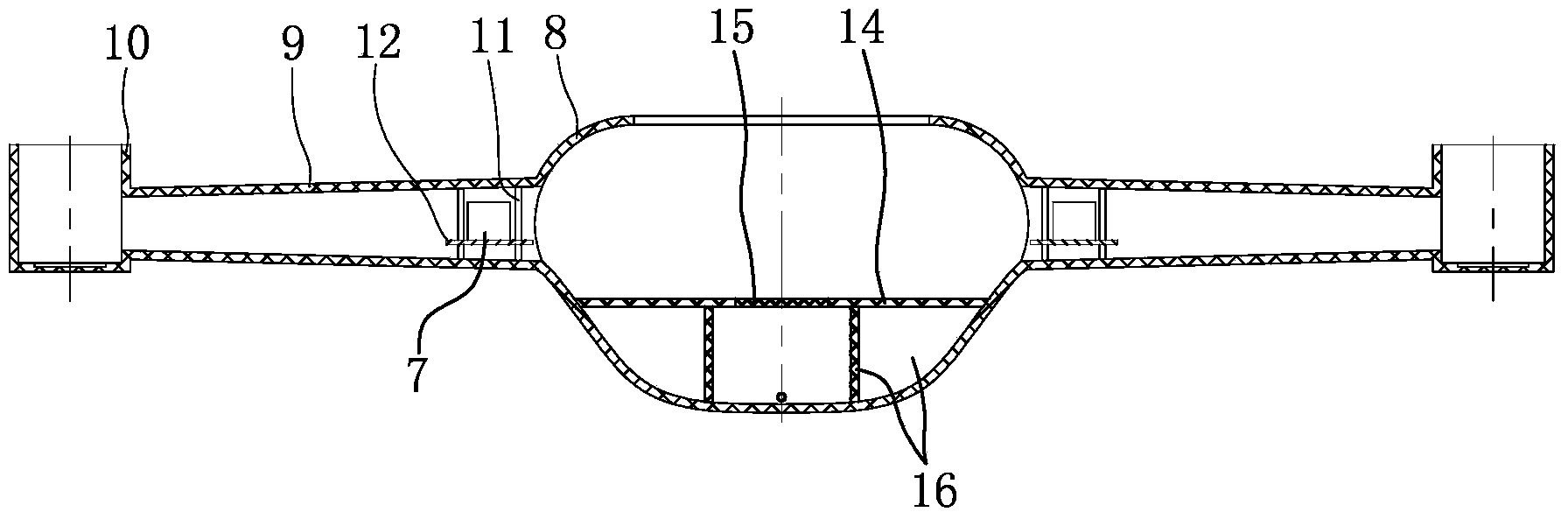
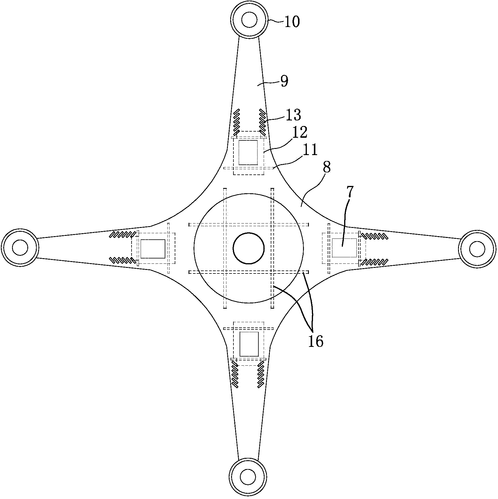
[0025] Such as figure 1 , figure 2 As shown, the fuselage is made of carbon fiber composite material and is composed of an equipment compartment 8 , a cantilever 9 and a motor compartment 10 . The equipment compartment 8 is located in the middle position, and the upper end of the equipment compartment 8 has a circular opening and the lower end is closed. The interior of the equipment compartment 8 is divided into an upper equipment cavity and a lower medicinal liquid cavity by a horizontal plate 14. The middle part of 14 has dosing mouth, and the small cover 15 that its shape size is adapted to is installed at this dosing mouth place. A "well"-shaped partition 16 is fixedly arranged in the liquid medicine cavity, and the partition 16 is made of honeycomb composite material with a thickness of 3-5mm. The partition 16 divides the liquid medicine cavity into ...


PUM


Abstract

The invention discloses a four-shaft type flight device body assembly which is characterized in that the inside of an equipment compartment (8) is separated into an upper equipment cavity and a lower medicine liquid cavity through a transverse plate (14); a motor bin (10) is formed in the outer end of each cantilever (9); a clamping block (2) and two location bases (3) are fixed at the position close to the edge of the bottom surface of a top cover (1); an inner support lug (3a) and an outer support lug (3b) are arranged at the inner end and the outer end of the bottom of each location base (3), respectively; a plug pin (4) penetrates through both the inner support lug and the outer support lug of the same location base (3); a poking rod (5) is vertically fixed to the plug pin (4); the plug pin (4) is sleeved with a spring (6). The four-shaft type flight device body assembly is simple in body shape, easy to process and manufacture, small in size, light in weight and reliable in strength; a medicine box filled with the medicine liquid is integrated in the body, thereby reducing the cost, reducing height size of the body, preventing the medicine liquid from rocking and ensuring balance of an aircraft.

Description

technical field [0001] The invention belongs to the technical field of agricultural aircraft, and in particular relates to an airframe assembly on a four-axis flying device. Background technique [0002] With the development of society and the advancement of science and technology, large-scale spraying of pesticides and fertilization on farmland are gradually completed by unmanned aerial vehicles. Both the top cover and the electronic governor are important parts of the agricultural unmanned aerial vehicle, wherein the top cover plays the role of sealing the port on the fuselage. The existing top cover has a flip structure and is locked by a lock. During use, the top cover is not only heavy and easily damaged; it is also extremely inconvenient to open and close, which is not only cumbersome to operate, but also time-consuming and labor-intensive, which greatly affects the convenience of use. However, the existing electronic governor is arranged in the equipment cabin, whic...

Claims


Application Information

Patent Timeline
Patent Type & Authority Applications(China)
IPC IPC(8): B64C1/06
Inventor 戴相超
Owner CHONGQING KINGTEC AVIATION IND
Why Eureka
Try Eureka