
Bead embroidery embroidering machine and bead feeding method

An embroidery machine and bead technology, which is applied in the bead embroidery machine and bead feeding field, can solve the problems of difficult to meet the required standards, uneven surface contours and pinholes of beads, and difficulty in precise positioning.

Active Publication Date: 2014-06-18
诸暨市化工机械厂
View PDF9 Cites 33 Cited by
  • Summary
  • Abstract
  • Description
  • Claims
  • Application Information

AI Technical Summary

Problems solved by technology

Embroidery beads have always been a problem in the embroidery machine industry, usually because the whole body of the embroidery beads is relatively uniform, mostly ellipsoid, sphere or cylinder, and the surface contour and pinhole of the beads are difficult to understand during the manufacturing and processing of small beads. Usually uneven, it is difficult to meet the required standards, so it is difficult to accurately locate, and it is difficult to accurately match the pinholes on the embroidery beads with the embroidery needles

Method used


Image

  • Bead embroidery embroidering machine and bead feeding method
  • Bead embroidery embroidering machine and bead feeding method
  • Bead embroidery embroidering machine and bead feeding method

Examples


Embodiment Construction

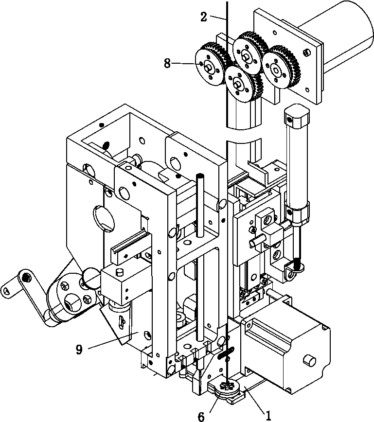
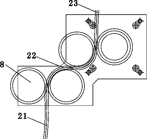
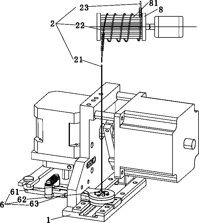
[0029] See Figure 1-11 This embodiment includes the machine body, one or more machine heads 9 are provided on the machine body, and the machine head 9 is connected with a feeding mechanism 1 that conveys embroidery beads one by one to the position directly below the embroidery needle 92 of the embroidery machine. The feeding mechanism 1 can It is arranged on the machine head 9 by sliding guide rails or double connecting rods so as to be separated from the machine head 9 when not working. The feeding mechanism 1 is provided with a clamping port for conveying embroidery beads. A bead guide rod 2 that continuously supplies embroidery beads to the feeding mechanism is suspended above the feeding mechanism 1. The bead guide rod 2 is threaded with embroidery beads to form a bead string. The bead string cooperates with the feeding mechanism 1 to continuously provide embroidery beads. The embroidery beads will drop their own weight to the corresponding place of the feeding mechanism...


PUM


Abstract

The invention discloses a bead embroidery embroidering machine. The bead embroidery embroidering machine comprises an engine body, wherein the engine body is provided with one or more than one machine head; the machine head is connected with a feeding mechanism for gradually conveying embroidery beads to a position right below an embroidering needle of the embroidering machine one by one; the feeding mechanism is provided with a clamping opening for clamping and positioning the embroidery beads; a bead guide rod for supplying the embroidery beads to the feeding mechanism is suspended above the feeding mechanism; the embroidery beads are threaded on the bead guide rod to form a bead cluster; a positioning structure for positioning the embroidery beads which need to slide to corresponding feeding positions of the feeding mechanism from the bead guide rod is further arranged above the feeding mechanism; the positioning center of the positioning structure and the positioning center of the clamping structure are concentric. The bead guide rod is provided with the bead cluster formed by the embroidery beads and the bead cluster can be continuously fed to the feeding mechanism; the bead guide rod and the positioning structure can be used for accurately positioning the embroidery beads so that the embroidery beads accurately slide into the corresponding parts of the feeding mechanism according to requirements and the embroidery beads are conveniently and accurately positioned and conveyed, and furthermore, the embroidering needle can accurately penetrate through needle holes in the embroidery beads to embroider the embroidery beads on a textile.

Description

Technical field [0001] The invention relates to a bead embroidery machine and a method for feeding beads. Background technique [0002] Embroidering beads on the fabric can achieve a better three-dimensional decorative effect, and more high-end glass beads are mostly embroidered on the fabric by hand. Embroidering beads on embroidery machines has always been a problem in the embroidery machine industry. It is usually due to the fact that the whole body of the beads is relatively uniform, mostly ellipsoid, sphere or cylinder, and the surface contours and pinholes of the beads in the manufacture of smaller beads. Usually uneven, it is difficult to achieve the required standard, so it is difficult to accurately locate, and it is difficult to accurately match the needle hole on the embroidery bead with the embroidery needle. Summary of the invention [0003] In order to solve the problems existing in the use of existing equipment, the present invention provides a bead embroidery mach...

Claims


Application Information

Patent Timeline
IPC IPC(8): D05C7/08D05C13/00
Inventor 骆建明袁伟青吴川川金学勇李利伟单建荣应雷鲁友强
Owner 诸暨市化工机械厂
Learn More