
Assembling and positioning device of middle door lock body for railway transportation

A technology for assembling positioning devices and railway transportation, which is applied in vehicle locks, building locks, locks, etc. It can solve the problems of damage to the lock cylinder installation device and troublesome operation, and achieve the effect of convenient operation and accurate positioning

Active Publication Date: 2014-06-18
蚌埠市瑞隆五金有限公司
View PDF8 Cites 0 Cited by
  • Summary
  • Abstract
  • Description
  • Claims
  • Application Information

AI Technical Summary

Problems solved by technology

[0003] During processing, use the push rod of the lock cylinder installation device to load the lock cylinder into the straight hole of the lock body. Before loading the lock cylinder, the lock body to be processed must be placed on the lower side of the lock cylinder installation device, and the lock body must be manually rotated. Angle, so that the straight hole position of the lock body is aligned with the push rod of the lock cylinder installation device, and the lock cylinder installation device is operated to press the lock cylinder into the straight hole of the lock body; but the above operation requires manual positioning of the lock body, which is troublesome to operate, and if Inaccurate positioning may easily cause damage to the lock cylinder installation device

Method used


Image

  • Assembling and positioning device of middle door lock body for railway transportation
  • Assembling and positioning device of middle door lock body for railway transportation

Examples


Embodiment Construction

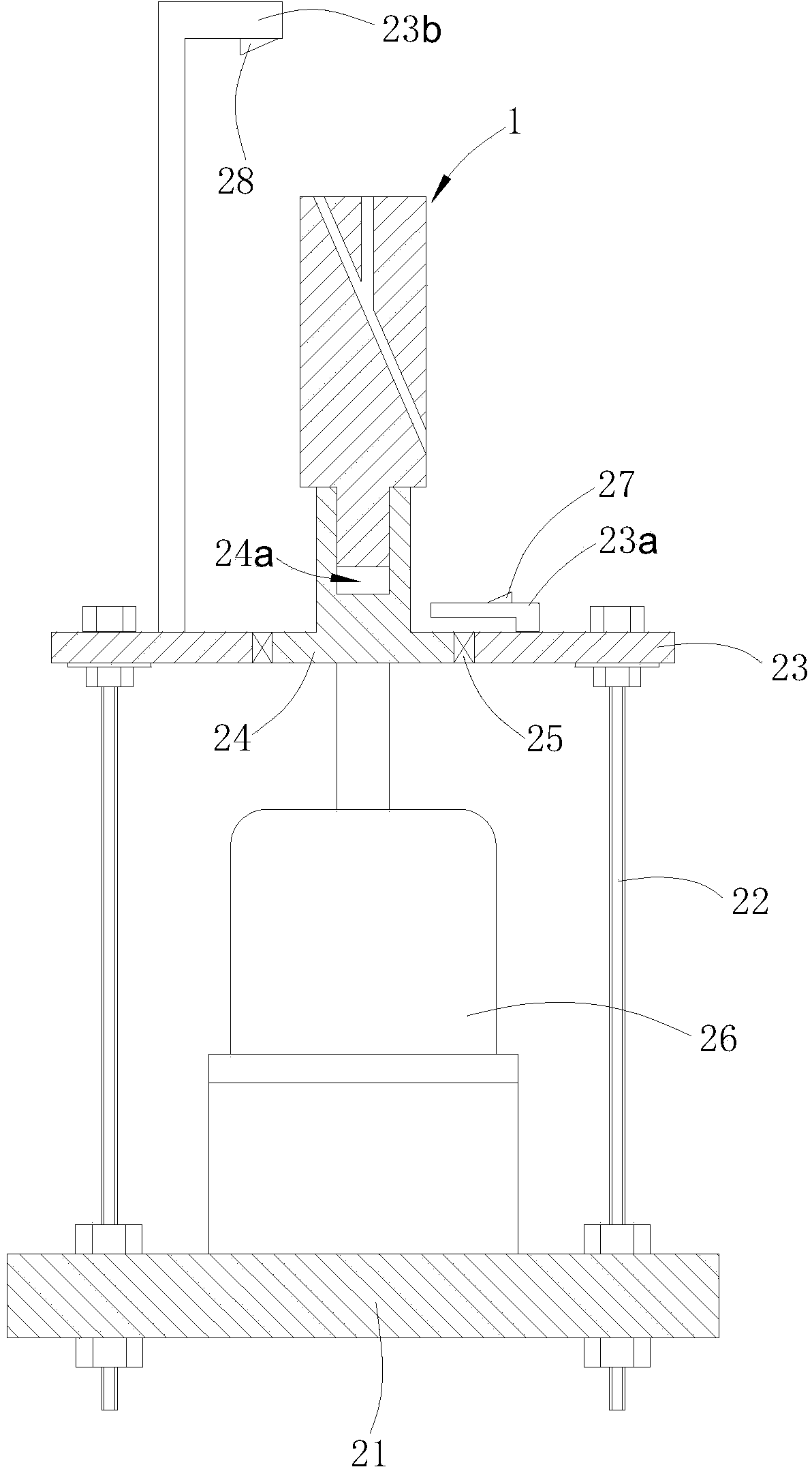
[0014] Such as figure 2 shown

[0015] The device comprises a base 21, a support 22, a rotating platform 23, a low-speed motor 26, a rotating base 24 and a photosensitive positioning assembly.

[0016] The base 21 is fixed with a support 22 by bolts, and the top of the support 22 is also horizontally fixed with a rotating platform 23 by bolts. The center of the rotating platform 23 is equipped with a rotating seat 24, and the rotating platform 23 cooperates with the rotating seat 24 through a bearing 25; Also vertically welded with low-speed motor 26, low-speed motor 26 is on the lower side of rotating platform 23, and the rotating shaft of low-speed motor 26 is connected with the center of the lower end surface of rotating base 24, so that the rotating shaft of low-speed motor 26 and rotating base 24 coaxially rotate, and rotating base The upper end surface of 24 is provided with a groove 24a fitting the head 11 of the middle door lock body 1 .

[0017] An infrared emittin...


PUM


Abstract

An assembling and positioning device of a middle door lock body for railway transportation. The assembling and positioning device of the middle door lock body for railway transportation comprises a support, a rotating platform, a motor, a rotating seat and a light sensation positioning assembly. The rotating platform is fixed on the upper portion of the support, the rotating seat is mounted on the rotating platform, a groove for placing of the head of the lock body is formed in the upper end face of the rotating seat, and a rotating shaft of the motor is connected with the lower end of the rotating seat. The light sensation positioning assembly comprises an infrared transmitting tube and an infrared receiving tube, the transmitting line and the receiving line of the infrared transmitting tube and the infrared receiving tube are consistent with the direction of the axis of an oblique hole in the lock body, and the infrared receiving tube is connected with the motor. The lock body is mounted on the rotating seat, the motor drives the rotating seat to rotate, the rotating seat drives the lock body to rotate, when the lock body rotates to a specific angle, light emitted by the infrared transmitting tube penetrates through the oblique hole to be captured by the infrared receiving tube, the infrared receiving tube is connected with the motor, an outside control circuit senses and controls the motor to stop rotating, and positioning operation of the lock body is achieved. The assembling and positioning device of the middle door lock body for railway transportation is convenient to operate and accurate to position.

Description

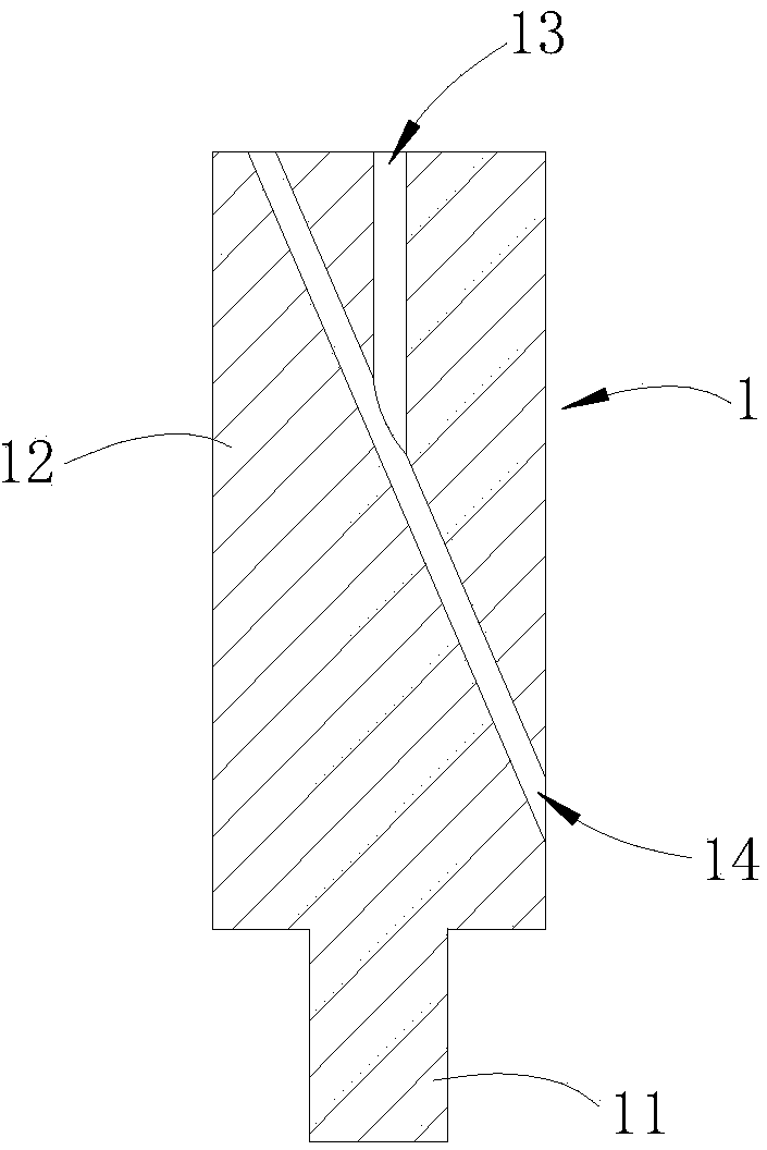
technical field [0001] The invention relates to a lock body locating device in the process of locking for railway transportation, in particular to a lock body assembling and positioning device for railway transportation. Background technique [0002] The middle door lock is a disposable lock widely used on freight trains, which includes a lock body, a lock cylinder and a chain, such as figure 1 As shown, the lock body 1 is a two-stage stepped shaft at the beginning and the end. The diameter of the head 11 of the lock body 1 is smaller than the diameter of the tail portion 12. There is a section of oblique hole 14 and a section of straight hole 13 in the lock body 1. An opening of the oblique hole 14 is in the lock. On the side wall of body 1 afterbody 12, the other opening of oblique hole 14 is on the end face of lock body 1 afterbody 12, and one end opening of straight hole 13 is on the end face of lock body 1 afterbody 12, and the other end of straight hole 13 and oblique ...

Claims


Application Information

Patent Timeline
IPC IPC(8): E05B79/02
Inventor 刘传让丁宁丁甸丁跃生陈云帮崔洁
Owner 蚌埠市瑞隆五金有限公司
Learn More