Variable cycle engine with high bypass ratio

A technology with variable cycle engine and large bypass ratio, which is applied in the direction of machine/engine, jet propulsion, etc., can solve the problems of airflow matching of engine components, and achieve the effect of improving airflow matching and improving surge margin.

Active Publication Date: 2014-06-18
AECC COMML AIRCRAFT ENGINE CO LTD
View PDF7 Cites 20 Cited by
  • Summary
  • Abstract
  • Description
  • Claims
  • Application Information

AI Technical Summary

Problems solved by technology

[0007] The purpose of the present invention is to propose a large bypass ratio variable cycle engine, which can solve

Method used


Image

  • Variable cycle engine with high bypass ratio
  • Variable cycle engine with high bypass ratio
  • Variable cycle engine with high bypass ratio

Examples


Embodiment Construction

[0032] The technical solutions of the present invention will be described in further detail below with reference to the accompanying drawings and embodiments.

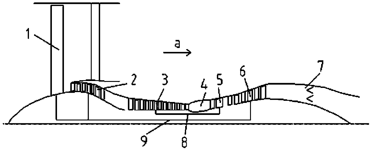
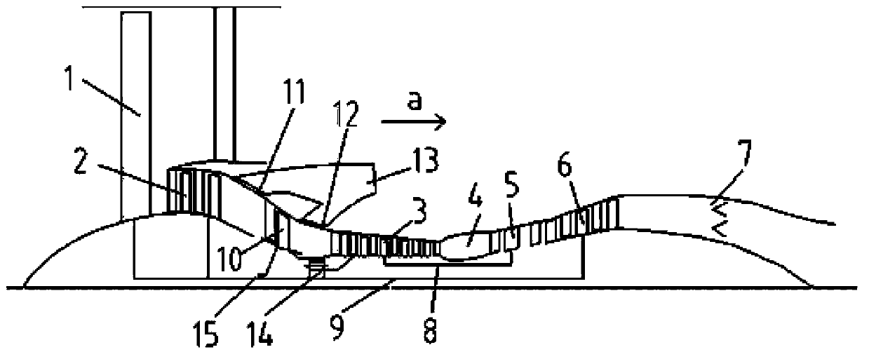
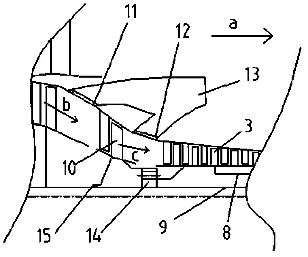
[0033] Such as figure 2 Shown is a schematic structural view of an embodiment of the large bypass ratio variable cycle engine of the present invention. In this embodiment, according to the flow direction a of the airflow along the axial direction, it includes: a front fan 1, a booster stage 2, a rear fan 10, a high-pressure compressor 3, a combustion chamber 4, a high-pressure turbine 5, a low-pressure turbine 6 and a rear fan. Nozzle7. The high-pressure turbine 5 and the low-pressure turbine 6 drive the high-pressure compressor 3 and the booster stage 2 through the high-pressure shaft 8 and the low-pressure shaft 9 respectively. The high-pressure compressor 3 is used to compress the airflow entering the core machine. Combustion chamber 4 accommodates the combustion of an incoming mixture of fuel and compressed air...


PUM


Abstract

The invention relates to a variable cycle engine with a high bypass ratio. The variable cycle engine comprises a front fan (1), a booster stage (2), a high-pressure compressor (3), a combustor (4), a high pressure turbine (5), a low-pressure turbine (6) and a tail pipe nozzle (9), wherein the high-pressure compressor (3) and the booster stage (2) are respectively driven by the high pressure turbine (5), the low-pressure turbine (6) and the exhaust nozzle (9) through a high pressure shaft (8) and a low pressure shaft (9); a rear fan (10) is arranged between the booster stage (2) and the high-pressure compressor (3), the revolving speed of the rear fan (10) is between the revolving speed of the booster stage (2) and the revolving speed of the high-pressure compressor (3), and a plurality of first bypass valves (12) and corresponding bypass channels are arranged on the outlet of the rear fan (10). The air current matching of engine parts can be improved by additionally setting the rear fan between the booster stage and the high-pressure compressor, and bypass valves capable of being opened or closed are arranged on the outlet of the rear fan, so that the bypass ratio of the engine can be changed so as to be applied to the requirements of different power states.

Description

technical field [0001] The invention relates to the field of gas turbine engine structure design, in particular to a large bypass ratio variable cycle engine. Background technique [0002] Such as figure 1 As shown in FIG. 1 , it is a structural schematic diagram of an existing common high bypass ratio turbofan engine. According to the axial flow direction a of the air flow, the structure consists in sequence of a large-sized front fan 1, a booster stage 2, a high-pressure compressor 3 for compressing the air flow entering the core engine, a combustion space for supplying a mixture of fuel and compressed air The combustion chamber 4, the high-pressure turbine 5 and the low-pressure turbine 6 rotated by the propelling airflow, and the tail nozzle 7 for the high-speed ejection of the turbine outlet airflow, the propelling airflow passes through the high-pressure shaft 8 and the low-pressure shaft 9 respectively, driving the high-pressure compressor 3 and booster Level 2. ...

Claims


Application Information

Patent Timeline
IPC IPC(8): F02K3/065F02K3/075
Inventor 张荣魏芳侯亮张颖侯灵峰
Owner AECC COMML AIRCRAFT ENGINE CO LTD
Why Eureka
Try Eureka