Backlight frame, backlight structure and liquid crystal display device

A backlight and frame technology, applied in the field of display, can solve the problems of injection molding retaining wall structure, high requirements for operators, and low accuracy, and meet the needs of narrow frame design, accurate alignment installation, and realization of alignment installation Effect

Active Publication Date: 2017-06-23
BOE TECH GRP CO LTD +1
View PDF18 Cites 0 Cited by
  • Summary
  • Abstract
  • Description
  • Claims
  • Application Information

AI Technical Summary

Problems solved by technology

[0003] At present, an important development trend of liquid crystal display devices such as mobile phones, tablets, and TVs is narrow bezels. A common narrow bezel product such as image 3 As shown, the length and width of the glass substrate 1 are slightly smaller than the length and width of the backlight composed of the light guide plate 4 and the optical film material 3, generally about 0.1 mm. At this time, it is impossible to inject the retaining wall structure 51 on the frame body 5. like Figure 4 shown
[0004] In the assembly process, the narrow frame products without retaining walls on the frame body need automatic line alignment assembly or use special jigs to assemble, which increases the cumbersomeness of the assembly team and the production cost, but the manual assembly has low accuracy. , Too high requirements for operators, etc.

Method used


Image

  • Backlight frame, backlight structure and liquid crystal display device
  • Backlight frame, backlight structure and liquid crystal display device
  • Backlight frame, backlight structure and liquid crystal display device

Examples


Embodiment Construction

[0026] The specific implementation manners of the present invention will be further described in detail below in conjunction with the accompanying drawings and embodiments. The following examples are used to illustrate the present invention, but are not intended to limit the scope of the present invention.

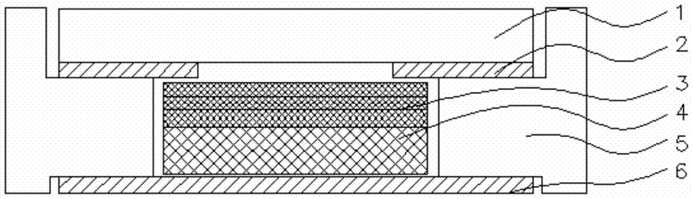
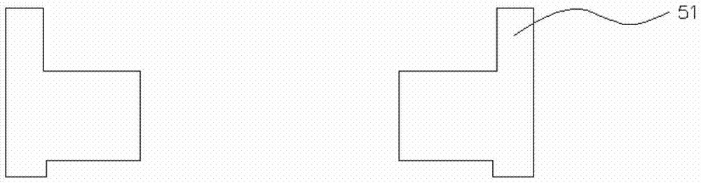
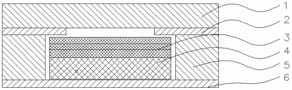
[0027] In order to meet the requirements of accurate alignment of the reflective sheet, light-shielding tape or glass substrate in the backlight structure when they are assembled with the backlight frame main body, and to avoid the impact on the narrow frame structure of the display device due to the setting of the retaining wall structure, the present invention A backlight frame is designed, which includes: a frame main body and a plurality of limiting structures arranged outside the frame main body, one end of the limiting structure is detachably connected to the frame main body, and a limiting part is provided at the other end to limit the The limiting surface of the po...


PUM


Abstract

The invention discloses a backlight source frame, a backlight source structure and a liquid crystal display device. The backlight source frame includes a frame body and a plurality of limit structures arranged outside the frame body. One end of the limit structures is connected to the frame body. In the peelable connection, the other end is provided with a limiting portion, and the limiting surface of the limiting portion is coplanar with the side surface of the frame body and is located above the side surface of the frame body. In the present invention, a peelable limit structure is provided on the frame body of the backlight source frame, and the limit structure is used to limit the position of the display elements that need to be formed on the frame body when assembling. It can bring convenience of operation to the staff; the peelable setting of the limit structure does not increase the width of the frame body, and can meet the needs of narrow frame design.

Description

technical field [0001] The invention relates to the field of display technology, in particular to a backlight source frame, a backlight source structure and a liquid crystal display device. Background technique [0002] Generally, the structure of a liquid crystal display device with retaining walls around the glass substrate is as follows: figure 1 As shown, we can see that when the backlight structure is assembled, the reflective sheet 6 is arranged on one side of the light guide plate 4, the optical film material 3 is arranged on the other side, and the frame main body 5 is arranged on the outside of the light guide plate 4 and the optical film material 3. A light-shielding tape 2 is arranged above the frame body 5, and the light-shielding tape 2 blocks the joint between the optical film material 3 and the frame body 5, and the glass substrate 1 is placed above the light-shielding tape 2. In order to facilitate the assembly of the light-shielding tape 2, the glass substra...

Claims


Application Information

Patent Timeline
Patent Type & Authority Patents(China)
IPC IPC(8): G02F1/1333
CPCG02F1/133308G02F1/133322F21V21/00G02F1/13332
Inventor 王子健王寰宇
Owner BOE TECH GRP CO LTD
Why Eureka
Try Eureka