
Display panel and manufacturing method thereof

A technology for display panels and manufacturing methods, which is applied in semiconductor/solid-state device manufacturing, electrical components, electric solid-state devices, etc., and can solve problems affecting the display effect of display panels and increasing border areas, etc.

Pending Publication Date: 2021-10-08
HEFEI VISIONOX TECH CO LTD
View PDF0 Cites 0 Cited by
  • Summary
  • Abstract
  • Description
  • Claims
  • Application Information

AI Technical Summary

Problems solved by technology

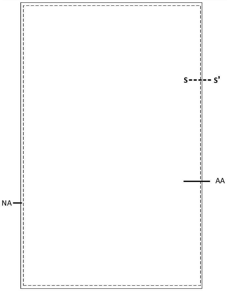
[0005] Based on this, it is necessary to address the problem that the setting of the packaging dam will increase the width of the frame area and affect the display effect of the display panel, and provide a display panel, which further includes:

Method used


Image

  • Display panel and manufacturing method thereof
  • Display panel and manufacturing method thereof
  • Display panel and manufacturing method thereof

Examples


Embodiment Construction

[0035] In order to facilitate the understanding of the present invention, the present invention will be described more fully below with reference to the associated drawings. Preferred embodiments of the invention are shown in the accompanying drawings. However, the present invention can be embodied in many different forms and is not limited to the embodiments described herein. On the contrary, these embodiments are provided to make the understanding of the disclosure of the present invention more thorough and comprehensive.

[0036] It should be noted that when an element is referred to as being “fixed” to another element, it can be directly on the other element or there can also be an intervening element. When an element is referred to as being "connected to" another element, it can be directly connected to the other element or intervening elements may also be present. The terms "vertical," "horizontal," "left," "right," and similar expressions are used herein for purposes ...


PUM


Abstract

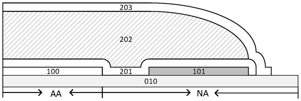
The invention relates to a display panel and a manufacturing method thereof. The display panel comprises a display area and a frame area, and comprises an array substrate, a pixel layer comprising a first pixel located in the display area and a second pixel located in a non-display area and arranged on one side of the array substrate, a first inorganic layer arranged on the side, away from the array substrate, of the pixel layer and covering the pixel layer, an organic layer with the orthographic projection on the array substrate at least covering the orthographic projection of the first pixel on the array substrate and arranged on the side, away from the pixel layer, of the first inorganic layer, and a second inorganic layer arranged on the side, away from the first inorganic layer, of the organic layer and covering the organic layer and the first inorganic layer. The second pixel includes an ultraviolet light emitting layer. By arranging the ultraviolet light emitting layer, the organic layer located on the side, away from the array substrate, of the second pixel in the frame area is preferentially cured, the organic layer is prevented from overflowing in the direction away from the display area, meanwhile, the width of the frame is not increased, and the narrow frame effect is better achieved.

Description

technical field [0001] The present invention relates to the field of display technology, in particular to a display panel and a manufacturing method thereof. Background technique [0002] OLED (Organic light-emitting diode, organic light-emitting diode) display panel has been widely promoted due to its advantages of low power consumption, high saturation, wide viewing angle, thin thickness, and flexibility. [0003] In today's development trend, OLED display panels are developing in the direction of flexibility. In an OLED display panel, a thin-film encapsulation structure is usually prepared on one side of the light-emitting device. In the thin-film encapsulation structure, inorganic materials and organic materials are stacked. modulus, so that on the basis of ensuring the bendability of the display panel, it can effectively block the erosion of oxygen and water vapor, and reduce the risk of damage and failure of the display panel. [0004] However, in the existing displa...

Claims


Application Information

Patent Timeline
IPC IPC(8): H01L51/52H01L51/56H01L27/32
CPCH10K59/12H10K50/844H10K71/00
Inventor 赵理张浩瀚李明宸张庆宇曹方义肖一鸣
Owner HEFEI VISIONOX TECH CO LTD
Learn More