Anti electric wall circuit for leakage protection switch and application of the same
A technology of leakage protection switch and leakage protection, which is applied in the direction of emergency protection circuit device, protection that responds to fault current, circuit device, etc., can solve the problems of inability to protect against leakage, hurt people with electricity, hurt people with electric shock, etc., and achieve protection The effect of safe electricity use, simple sampling circuit and low production cost
- Summary
- Abstract
- Description
- Claims
- Application Information
AI Technical Summary
Problems solved by technology
Method used
Image

Examples
Embodiment Construction
[0018] The present invention will be further described in detail below in conjunction with the accompanying drawings and specific embodiments.
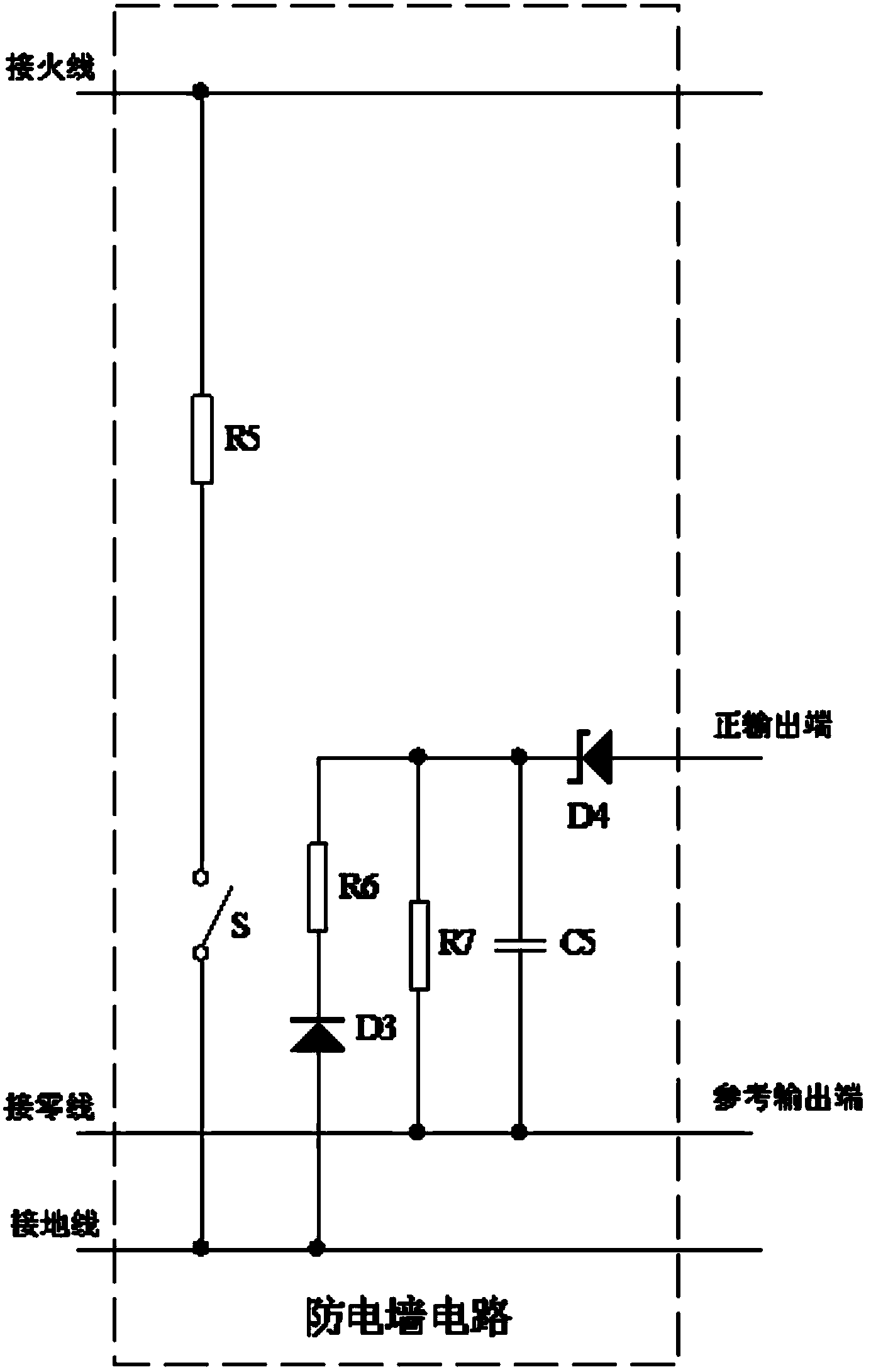
[0019] Such as figure 1 As shown, the electric wall circuit of the leakage protection switch of the present invention includes a voltage divider circuit composed of resistor R6 and resistor R7, a diode D3 as a rectifier circuit, a filter capacitor C5 as an output circuit, a voltage regulator diode D4 and a neutral line input, ground input and protection output. Resistor R6 and resistor R7 are respectively the first voltage dividing part and the second voltage dividing part of the voltage dividing circuit, the first end of the resistor R6 is connected to the cathode of the diode D3, and the anode of the diode D3 is connected to the input terminal of the ground wire; The first end of R7 is connected to the neutral line input end; the second end of the resistor R7 is connected to the second end of the resistor R6. The second end of the...
PUM
 Abstract
Description
Claims
Application Information
 - R&D
- Intellectual Property
- Life Sciences
- Materials
- Tech Scout
- Unparalleled Data Quality
- Higher Quality Content
- 60% Fewer Hallucinations
Browse by: Latest US Patents, China's latest patents, Technical Efficacy Thesaurus, Application Domain, Technology Topic, Popular Technical Reports.
© 2025 PatSnap. All rights reserved.Legal|Privacy policy|Modern Slavery Act Transparency Statement|Sitemap|About US| Contact US: help@patsnap.com