Tyre comprising a layer of circumferential reinforcing elements

A technology of reinforcing elements, reinforcements, applied in the direction of reinforcement layers of pneumatic tires, special tires, heavy-duty tires, etc., can solve problems such as adverse effects of durability, increase in mileage, etc.

Active Publication Date: 2014-06-18
MICHELIN & CO CIE GEN DES ESTAB MICHELIN
View PDF13 Cites 18 Cited by
  • Summary
  • Abstract
  • Description
  • Claims
  • Application Information

AI Technical Summary

Problems solved by technology

The combination of conditions in which such tires are driven undoubtedly results in increased miles driven and reduced wear on the tires; on the other hand, the durability of the tires and especially the crown reinforcement is adversely affected

Method used


Image

  • Tyre comprising a layer of circumferential reinforcing elements
  • Tyre comprising a layer of circumferential reinforcing elements
  • Tyre comprising a layer of circumferential reinforcing elements

Examples


Embodiment Construction

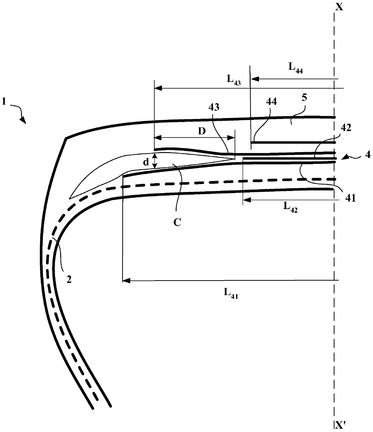
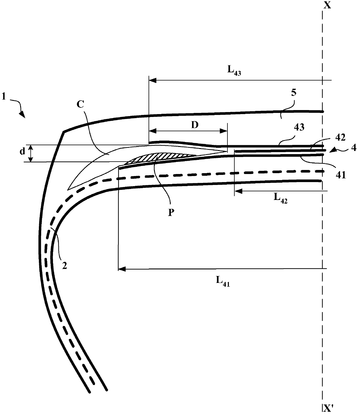
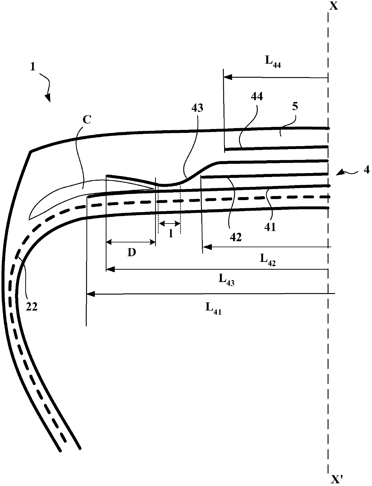
[0163] The figures are not drawn to scale for ease of understanding. The figures represent only a half-view of a tyre, which extends symmetrically with respect to an axis XX' representing its circumferential median plane or equatorial plane.

[0164] exist figure 1 In , a tire 1 of size 315 / 70R22.5 has an aspect ratio H / S equal to 0.70, where H is the height of the tire 1 on its mounted rim and S is its maximum axial width. Said tire 1 comprises radial carcass reinforcement 2 anchored in two beads (not shown in the figures). The carcass reinforcement is formed from a single layer of metal cords. Said carcass reinforcement 2 is hooped by a crown reinforcement 4 formed radially from the inside to the outside by:

[0165] - a first working layer 41 formed of unhooped, inextensible metal cords 9.28 continuous over the entire width of the ply and oriented at an angle equal to 24°,

[0166] - a layer 42 of circumferential reinforcing elements formed of steel metal cords 21x23 o...


PUM


Abstract

The invention relates to a tyre comprising a crown reinforcement formed of at least two working crown layers of reinforcing elements, a first layer C of rubber compound being positioned between at least the ends of said at least two working crown layers, and the crown reinforcement comprising at least one layer of metal circumferential reinforcing elements. According to the invention, the elastic modulus at 10% tensile strain of the first layer C is less than 8 MPa and the maximum value of tan(delta), denoted tan(delta) max, of the first layer C is less than 0.100.

Description

technical field [0001] The present invention relates to tires with radial carcass reinforcement, in particular tires intended to equip vehicles carrying heavy loads traveling at sustained speeds, such as vans, tractors, trailers, or buses. Background technique [0002] Usually, in tires of the heavy-duty type, the carcass reinforcement is anchored on either side in the bead area and is radially covered by a crown reinforcement consisting of at least two superimposed The layers are formed by threads or cords parallel in each layer and crossing from one layer to the next so as to form an angle with the circumferential direction of between 10° and 45°. Said working layer forming a working reinforcement may also be covered by at least one "protective" layer, advantageously formed by metallic and stretchable (called elastic) reinforcing elements. It may also comprise a layer of low-stretch metal threads or cords forming an angle between 45° and 90° with the circumferential direc...

Claims


Application Information

Patent Timeline
Patent Type & Authority Applications(China)
IPC IPC(8): B60C1/00B60C9/18B60C9/20
CPCB60C2200/06B60C2009/2016B60C2009/1842B60C1/00B60C9/1835B60C9/185B60C2009/2019B60C2009/2061B60C2009/2051B60C2009/2064B60C9/2006B60C9/18B60C2009/1864
Inventor A·多明戈J·贝松F·巴尔巴林G·萨拉R·C·勒杜列斯库
Owner MICHELIN & CO CIE GEN DES ESTAB MICHELIN
Why Eureka
Try Eureka