Novel structure for forging claw beam part of charging and discharging machine

A new structure, loading and unloading technology, applied in forging/pressing/hammer devices, manufacturing tools, operating devices, etc., can solve the problems of poor flexibility, single action of the clamp rod, limited angle and stroke of the clamp rod, etc., and achieve stable performance Reliable, increased angle range, flexible adjustment effect

Active Publication Date: 2014-06-25
山东荣升重型机械股份有限公司
View PDF8 Cites 6 Cited by
  • Summary
  • Abstract
  • Description
  • Claims
  • Application Information

AI Technical Summary

Problems solved by technology

Due to the single action of the clamp rod and poor flexibility, it cannot adapt to multi-angle operations
Although some improvements have been made to the action function of the pliers so far, most of them rely on the crank connecting rod structure, which is not only complex in structure and bulky, but also unable to adapt to frequent impacts of dynamic loads, poor fatigue resistance, and reliability. needs improvement
In addition, the driving form of the lifting and lowering of the clamp rod is hydraulic drive, limited by the formation of the hydraulic rod, the angle and stroke of the lifting and lowering of the clamp rod are limited

Method used


Image

  • Novel structure for forging claw beam part of charging and discharging machine
  • Novel structure for forging claw beam part of charging and discharging machine
  • Novel structure for forging claw beam part of charging and discharging machine

Examples


Embodiment Construction

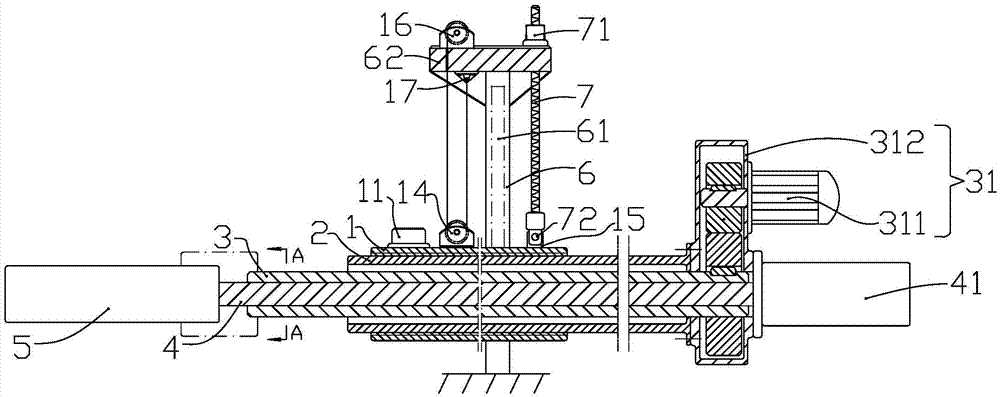
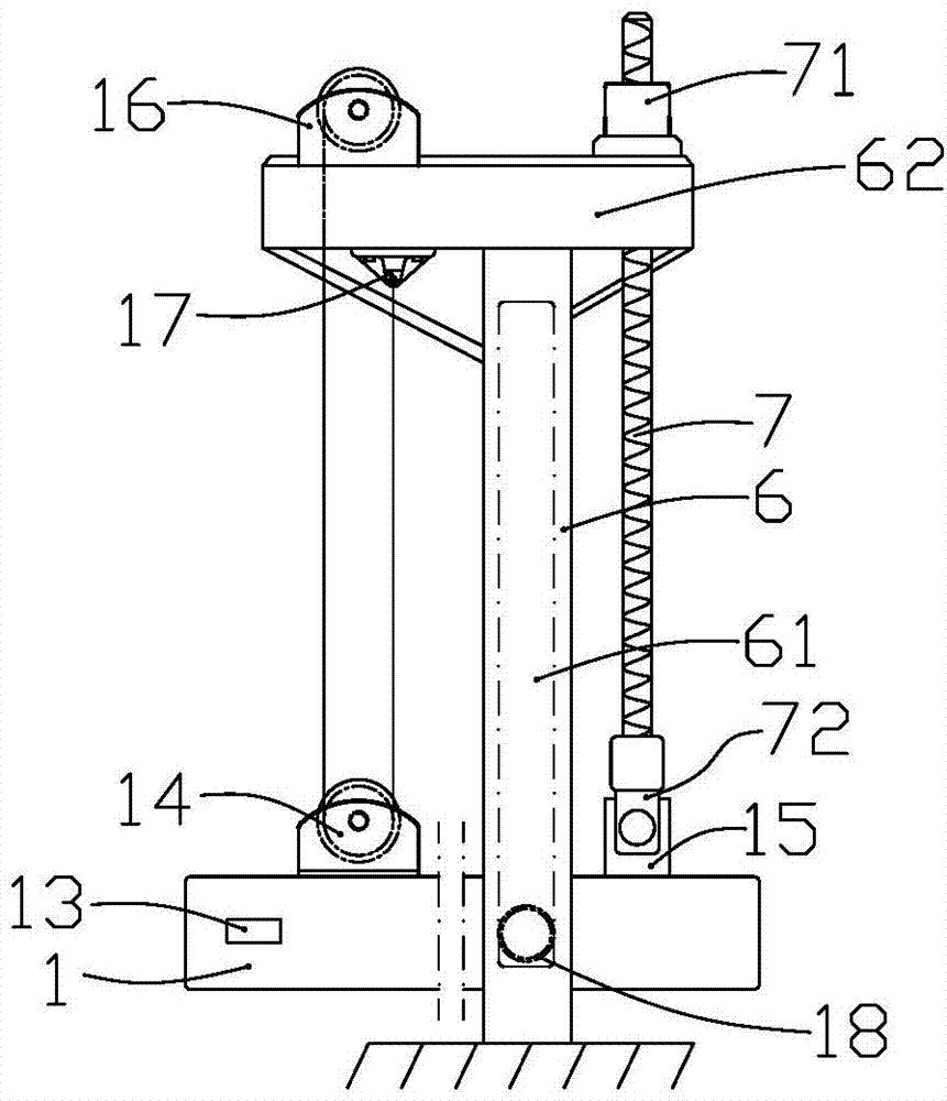
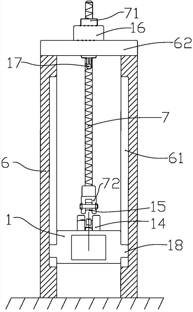
[0027] In order to facilitate the understanding of the technical solution of the present invention, the technical content involved in it will be further described below in conjunction with the accompanying drawings.

[0028] In describing the present invention, it should be noted that the orientation or position indicated by the terms "upper", "lower", "left", "right", "inner", "outer", "front", "back" etc. The relationship is based on the orientation or positional relationship shown in the drawings, and is only for the convenience of describing the present invention and simplifying the description, rather than indicating or implying that the referred device or element must have a specific orientation, be constructed and operated in a specific orientation, therefore It should not be construed as a limitation of the present invention.

[0029] In the description of the present invention, it should be noted that unless otherwise specified and limited, the terms "installation", "...


PUM


Abstract

The invention relates to a novel structure for forging a claw beam part of a charging and discharging machine. The novel structure comprises a guiding barrel, an expansion square barrel, a hollow shaft, a pull rod, a clamping oil cylinder, a clamping claw mechanism, a claw beam rotary driving device, a stand column and a nut lead screw assembly, the guiding barrel, the expansion square barrel, the hollow shaft and the pull rod are coaxially arranged, the expansion square barrel, the hollow shaft and the pull rod are associated with the claw beam rotary driving device to form a combined whole, can jointly move front and back along with the movement of the expansion square barrel, the hollow shaft and the pull rod can serve as a whole to conduct rotation in a plane perpendicular to the axial direction of the whole, meanwhile, the pull rod moves in the front-and-back direction relative to the hollow shaft, the lifting mode that a shaft rolling steel wire rope is matched with a lead screw is achieved, and the stroke distance of the claw beam in the vertical direction is obviously increased compared with the hydraulic mode. The functions of the claw opening clamping movement and the claw opening unclamping movement in the clamping claw mechanism are not influenced, meanwhile, chuck rotation, claw beam stretching, claw beam slanting and bending angle increasing and vertical stroke increasing can be completed, and the novel structure is simple in structure, compact in size and stable and reliable in performance.

Description

technical field [0001] The invention relates to the structure of the clamp rod part on the loading and unloading machine used in the forging production process, and belongs to the technical field of mechanical design. Background technique [0002] The domestic forging industry is currently under the dual pressure of overcapacity and the world financial crisis. If enterprises want to survive and develop in the current harsh situation, it is imperative to improve product quality and reduce production costs. Therefore, it is very necessary to improve the mechanization of production and reduce labor intensity and cost. [0003] At present, the loading and unloading machine for forging of automobile wheel hub is used to load the forged steel ingot or billet into the heating furnace, and can take the heated steel ingot or billet out of the heating furnace, and send it to the forging press or forging manipulator. . It is an important equipment in the forging process. The tong ba...

Claims


Application Information

Patent Timeline
Patent Type & Authority Applications(China)
IPC IPC(8): B21K27/00B21K1/40
Inventor 柏民
Owner 山东荣升重型机械股份有限公司
Why Eureka
Try Eureka