
Combined tunnel type guide limiting structure of die-casting mold

A die-casting mold and tunnel-type technology, which is applied in the field of combined tunnel-type guiding and limiting structures, achieves the effects of stable final size, improved production qualification rate, and improved service life

Active Publication Date: 2014-06-25
NINGBO XUNHUI ELECTRIC APPLIANCE
View PDF5 Cites 5 Cited by
  • Summary
  • Abstract
  • Description
  • Claims
  • Application Information

AI Technical Summary

Problems solved by technology

[0006] The technical problem to be solved by the present invention is to aim at the current state of the art that the above-mentioned mold slider is guided by a single guide rail, and provide a method that can prevent the slider from sliding out of order and the front edge from being stuck, reasonably control the final size change of the die-casting parts, and reduce die-casting defects. , a combined tunnel-type guiding and limiting structure of a die-casting mold to improve the qualified rate of die-casting production

Method used


Image

  • Combined tunnel type guide limiting structure of die-casting mold
  • Combined tunnel type guide limiting structure of die-casting mold
  • Combined tunnel type guide limiting structure of die-casting mold

Examples


Embodiment Construction

[0020] Embodiments of the present invention will be further described in detail below in conjunction with the accompanying drawings.

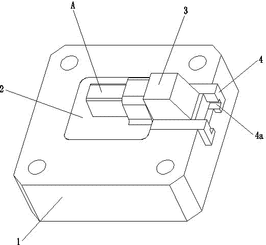
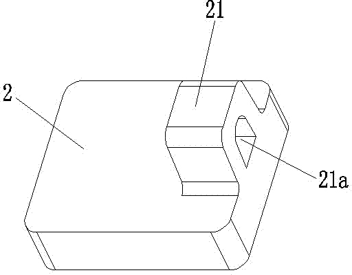
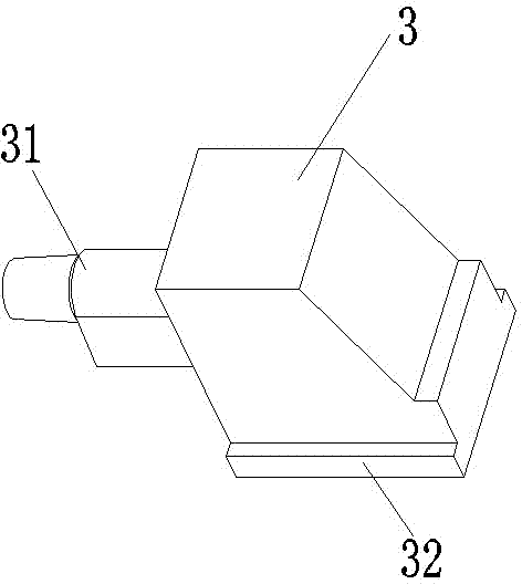
[0021] Figure 1 to Figure 4 It is a structural schematic diagram of the present invention.

[0022] The reference signs are: product part A, part hole K, movable mold frame 1, movable mold cavity 2, tunnel limit block 21, cavity tunnel 21a, core mold slider 3, slider core 31, guide rail convex Side 32, slider guide rail 4, guide rail groove 4a.

[0023] Such as Figure 1 to Figure 4 As shown, a combined tunnel-type guiding and limiting structure of a die-casting mold according to the present invention includes a movable mold frame 1 with a cavity positioning cavity in the center of the upper end surface, a movable mold cavity 2 and a core mold that match the die-casting product part A Slide block 3, the front end of mandrel mold slide block 3 is shaped on the slide block core 31 that is used for the part hole K of molding product part A.

...


PUM


Abstract

The invention discloses a combined tunnel type guide limiting structure of a die-casting mold. The combined tunnel type guide limiting structure of the die-casting mold comprises a movable mold frame with a mold cavity positioning concave cavity, a movable mold cavity and a core mold sliding block. The core mold sliding block is provided with a sliding block mold core, the movable mold cavity is installed in the mold cavity positioning concave cavity, the movable mold frame is provided with a guide sliding groove used for improving the sliding stability of the core mold sliding block, the core mold sliding block and the guide sliding groove are matched in a front-and-back sliding mode, the front end of the upper end face of the movable mold cavity is provided with a tunnel limiting block, the tunnel limiting block is provided with a mold cavity tunnel which forms a sliding block tunnel structure, the mold cavity tunnel is composed of a cylindrical sliding hole and a tunnel sliding hole, and the end face, where the cylindrical sliding hole is formed, of the tunnel limiting block is matched with the hole end face of a part hole of a product part in a limiting mode. According to the combined tunnel type guide limiting structure of the die-casting mold, the sliding block tunnel structure design is adopted, and a guide rail is provided so that the motion trail of the core mold sliding block can be limited through the cavity tunnel and the guide rail, position change caused by the core mold sliding block during mold sinking is effectively avoided, and the defects that the size of die castings is out of tolerance due to mold swelling of a movable mold and a fixed mold, the sliding block fails in sliding and inlet flashing is stuck are thoroughly overcome or improved.

Description

technical field [0001] The invention relates to the technical field of die-casting molds, in particular to the stability design of a slide block of a die-casting die, in particular to a combined tunnel-type guiding and limiting structure of a die-casting die. Background technique [0002] Die casting mold is a big category in mold. In recent years, with the rapid development of my country's automobile and motorcycle industries, the die-casting industry has ushered in a new period of development. But at the same time, higher requirements are put forward for the comprehensive mechanical properties, life and mold structure of die-casting molds. [0003] Die casting is a precise production process, however, there are many factors that can affect the final dimensional variation of die castings. Dimensional changes can be divided into linear changes (mainly caused by shrinkage), movement dislocation between molds, parting line, casting and mold warpage, die-casting parameters, c...

Claims


Application Information

Patent Timeline
Patent Type & Authority Applications(China)
IPC IPC(8): B22D17/24
Inventor 童建辉张祎陆如辉张文龙
Owner NINGBO XUNHUI ELECTRIC APPLIANCE
Learn More