Clamp for automatically inlaying cylindrical insert in mold

A technology for cylindrical inserts and molds, which is applied in the field of fixtures for automatically inserting cylindrical inserts in molds. It can solve problems such as accelerating mold wear, reducing mold service life, and operating errors, achieving accurate positioning and improving production efficiency. , Eliminate the effect of operational errors

Active Publication Date: 2014-06-25
威猛工业自动化系统(昆山)有限公司
View PDF3 Cites 11 Cited by
  • Summary
  • Abstract
  • Description
  • Claims
  • Application Information

AI Technical Summary

Problems solved by technology

[0002] The traditional method of placing cylindrical inserts in the cavity of the mold is usually manual. After the mold is opened, the worker first opens the front safety door of the mold and takes out the product from the cavity of the mold, and then manually places the cylindrical inserts into the mold. In the cavity, this method is not only inefficient, but also requires a production worker in the production process of the mold, which increases the production cost of the mold, and each mold needs to be opened and closed during the production process The front safety door is one time, which speeds up the wear of the mold and reduces the service life of the mold
[0003] In addition, in the production process of injection molded parts, once the working hours of workers are too long, they are prone to fatigue, prone to operational errors, and then reduce the production quality of products

Method used


Image

  • Clamp for automatically inlaying cylindrical insert in mold
  • Clamp for automatically inlaying cylindrical insert in mold
  • Clamp for automatically inlaying cylindrical insert in mold

Examples


Embodiment Construction

[0031] The technical solution of the present invention will be further described below in conjunction with the accompanying drawings and through specific implementation methods.

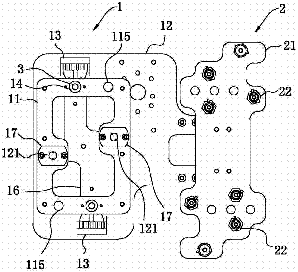
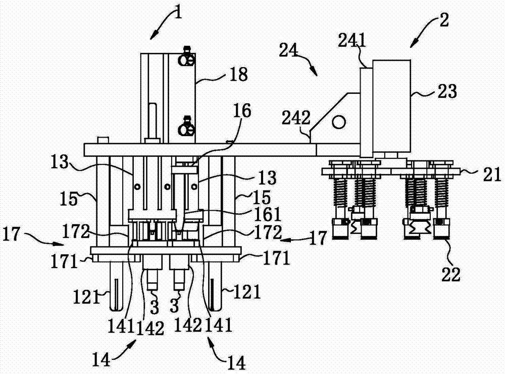
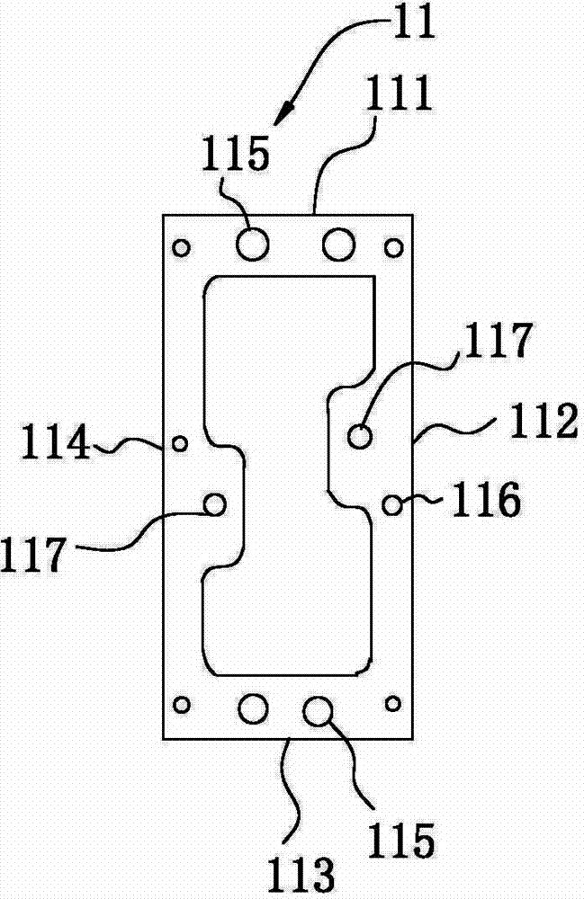
[0032] Such as Figure 1 to Figure 3 As shown, a fixture for automatically inserting a cylindrical insert 3 in a mold according to the present invention includes a clamping installation device 1 and an adsorption device 2. The clamping installation device 1 includes a front fixing plate 11 parallel to the front fixing plate 11. The rear fixed plate 12, the connection and positioning device for connecting the front fixed plate 11 and the rear fixed plate 12, the clamping device 13 and the thrust device, the front fixed plate 11 includes a first end 111, a second end adjacent to the first end 111 Two ends 112, a third end 113 opposite to the first end 111, and a fourth end 114 opposite to the second end 112, the first end 111 and the third end 113 are provided with a positioning hole 115 formed by one-...


PUM


Abstract

The invention discloses a clamp for automatically inlaying a cylindrical insert in a mold. The clamp comprises a clamping and mounting device and an adsorption device, wherein the clamping and mounting device comprises a front fixing plate, a rear fixing plate parallel to the front fixing plate, a connecting and positioning device used for connecting the front fixing plate and the rear fixing plate, a clamping device and a thrust device; the front fixing plate comprises a first end, a second end adjacent to the first end, a third end opposite to the first end, and a fourth end opposite to the second end; cylindrical insert positioning holes are formed in the first end and the third end; positioning pieces in which the cylindrical inserts can be arranged are arranged in the cylindrical insert positioning holes; the clamping device is fixedly arranged at a position, which corresponds to the positioning piece, on the rear fixing plate; the clamping device is used for clamping the cylindrical inserts arranged in the positioning pieces; the thrust device is fixed on the rear fixing plate and is used for ejecting the cylindrical inserts arranged in the positioning pieces into a cavity of the mold; the adsorption device is positioned on one side of the clamping and mounting device, is connected with the rear fixing plate and is used for removing ejected products from the cavity of the mold.

Description

technical field [0001] The invention relates to the field of fixtures, in particular to a fixture for automatically embedding cylindrical inserts in molds Background technique [0002] The traditional method of placing cylindrical inserts in the cavity of the mold is usually manual. After the mold is opened, the worker first opens the front safety door of the mold and takes out the product from the cavity of the mold, and then manually places the cylindrical inserts into the mold. In the cavity, this method is not only inefficient, but also requires a production worker in the production process of the mold, which increases the production cost of the mold, and each mold needs to be opened and closed during the production process The front safety door is once, which accelerates the wear of the mold and reduces the service life of the mold. [0003] In addition, in the production process of injection molded parts, once the working hours of workers are too long, they are prone ...

Claims


Application Information

Patent Timeline
Patent Type & Authority Applications(China)
IPC IPC(8): B29C45/17B29C45/43
CPCB29C45/14008B29C45/4005
Inventor 张小强
Owner 威猛工业自动化系统(昆山)有限公司
Why Eureka
Try Eureka