Method For Monitoring A Temperature Control Media Supply

A temperature-regulating medium and supply device technology, which is applied in the field of temperature-regulating medium supply devices, can solve problems such as pressure fluctuations that cannot be considered

Active Publication Date: 2014-06-25
ENGEL AUSTRIA
View PDF5 Cites 5 Cited by
  • Summary
  • Abstract
  • Description
  • Claims
  • Application Information

AI Technical Summary

Problems solved by technology

[0006] The disadvantage of this method is that the pressure in the inflow and return must be constant
Pressure fluctuations as often occur in practice cannot be taken into account

Method used


Image

  • Method For Monitoring A Temperature Control Media Supply
  • Method For Monitoring A Temperature Control Media Supply
  • Method For Monitoring A Temperature Control Media Supply

Examples


Embodiment Construction

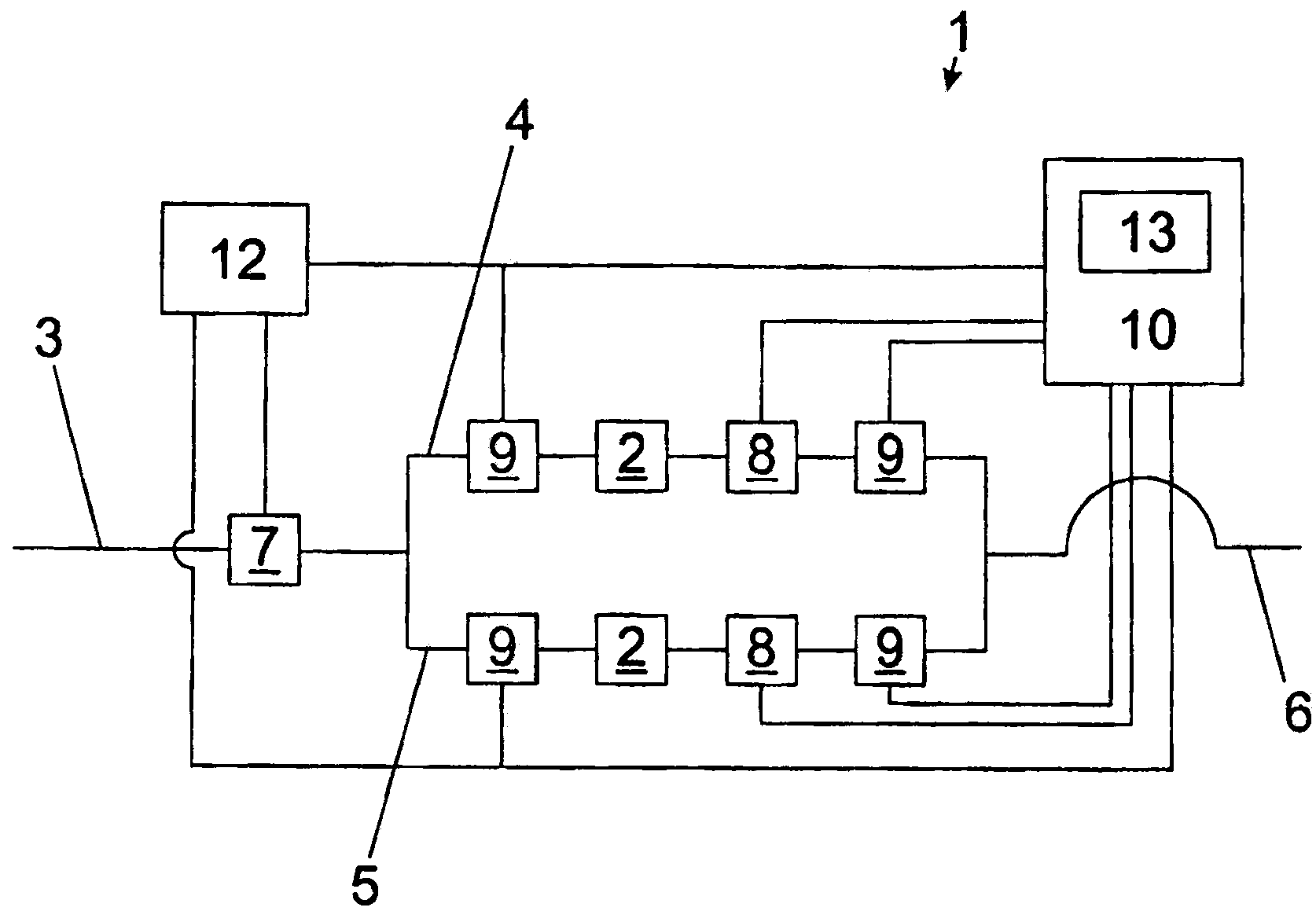
[0032] figure 1 In the figure, the inflow end 3 of the temperature control device 1 , the temperature control lines 4 and 5 and the return end 6 can be seen first. Tempering lines 4 and 5 pass through mold 2 , which is thereby tempered. Furthermore, two pressure sensors 9 and one flow sensor 8 are arranged in each of the temperature control lines 4 and 5 , which are respectively connected to an analysis device 10 . Analysis device 10 has screen 13, alarm signal or by means of formula The calculated hydraulic resistance can be displayed on this screen. In addition, an alarm signal can be displayed on the screen 13 when one of the hydraulic resistances R leaves an allowable range.

[0033] In this exemplary embodiment, the flow through the temperature control lines 4 , 5 is regulated by means of a flow control valve 7 . For this purpose, the control device 12 is connected not only to the flow regulating valve 7 but also to the two pressure sensors 9 .

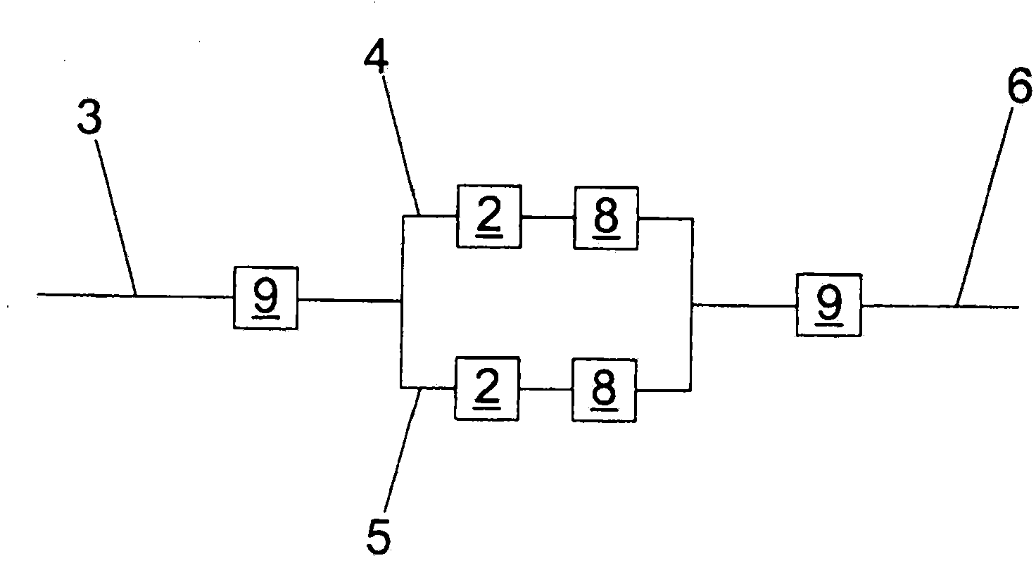
[0034] figure 2 A...


PUM


Abstract

In a method of monitoring an apparatus for temperature control media supply of a tool of an injection molding machine, the apparatus for temperature control media supply has a feed and a return, between which at least one temperature control conduit is arranged, wherein at least one through-flow sensor is arranged. At least one temperature control conduit. At least one pressure drop is measured in the at least one temperature control conduit. At least one hydraulic resistance and / or at least one resistance change in the at least one temperature control conduit is calculated on the basis of at least one volume flow measured with the at least one through-flow sensor and on the basis of the at least one measured pressure drop, and the at least one hydraulic resistance and / or the at least one resistance change is visually represented. The present invention also relates to a temperature adjusting medium supply device serves for the mold for the injection molding machine and mold temperature control medium, a method of injection molding machine.

Description

technical field [0001] The invention relates to a method for monitoring a tempering medium supply of a mold of an injection molding machine and to such a device. Background technique [0002] In plastics processing and especially in injection moulding, it is important that the molding tool (tool for short) be tempered accordingly, i.e. a specific temperature in the tool is kept constant during the production process by targeted supply and discharge of heat kept. To achieve this, channels are provided in the mold through which a fluid (mostly water) flows. These channels are also called tempering lines. Typically, multiple channels are supplied with an isothermal fluid such that each channel is fed from the inlet end and joins to the return end after passing through the mould. This distribution and collection of fluids is usually achieved by distributors in which eg pressure sensors or flow sensors are arranged. The applicant's AT12213U1 can be used as an example. [000...

Claims


Application Information

Patent Timeline
Patent Type & Authority Applications(China)
IPC IPC(8): B29C45/78
CPCB29C45/84B29C45/78B29C45/7306B29C2945/76531B29C2945/76732B29C2945/76006
Inventor F·拉施克K·滕茨勒
Owner ENGEL AUSTRIA
Why Eureka
Try Eureka