car bumper

A technology of buffers and automobiles, which is applied to bumpers and other directions, can solve the problems of pressure increase, conversion, and bulky volume of the spray chamber, and achieve the effects of reducing impact force, improving service life, and prolonging collision time

Active Publication Date: 2016-08-03
WM MOTOR TECH GRP CO LTD
View PDF6 Cites 0 Cited by
  • Summary
  • Abstract
  • Description
  • Claims
  • Application Information

AI Technical Summary

Problems solved by technology

That is to say, the piston compresses the oil to make it spray out from the small hole. Although there is energy consumption, the energy consumption is far from the kinetic energy generated at the moment of the car collision, that is, the kinetic energy generated by the car collision cannot be obtained by flow resistance transformed by
Therefore, it does not solve the problem
At the same time, in such a short period of time, if the liquid cannot be drained from the fuel injection port in time, the pressure in the liquid injection chamber will rise sharply, and the phenomenon of steel sleeve bursting is very likely to occur.
Furthermore, due to the existence of the fuel injection port, the above-mentioned buffer can only work under low pressure, and its volume will be very large, and it is very unrealistic to install it in the narrow space of the existing car body head or tail , so the implementation of the above scheme cannot achieve the expected effect

Method used


Image

  • car bumper
  • car bumper

Examples


Embodiment Construction

[0016] The present invention will be further described in detail below in conjunction with the accompanying drawings and specific embodiments.

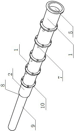
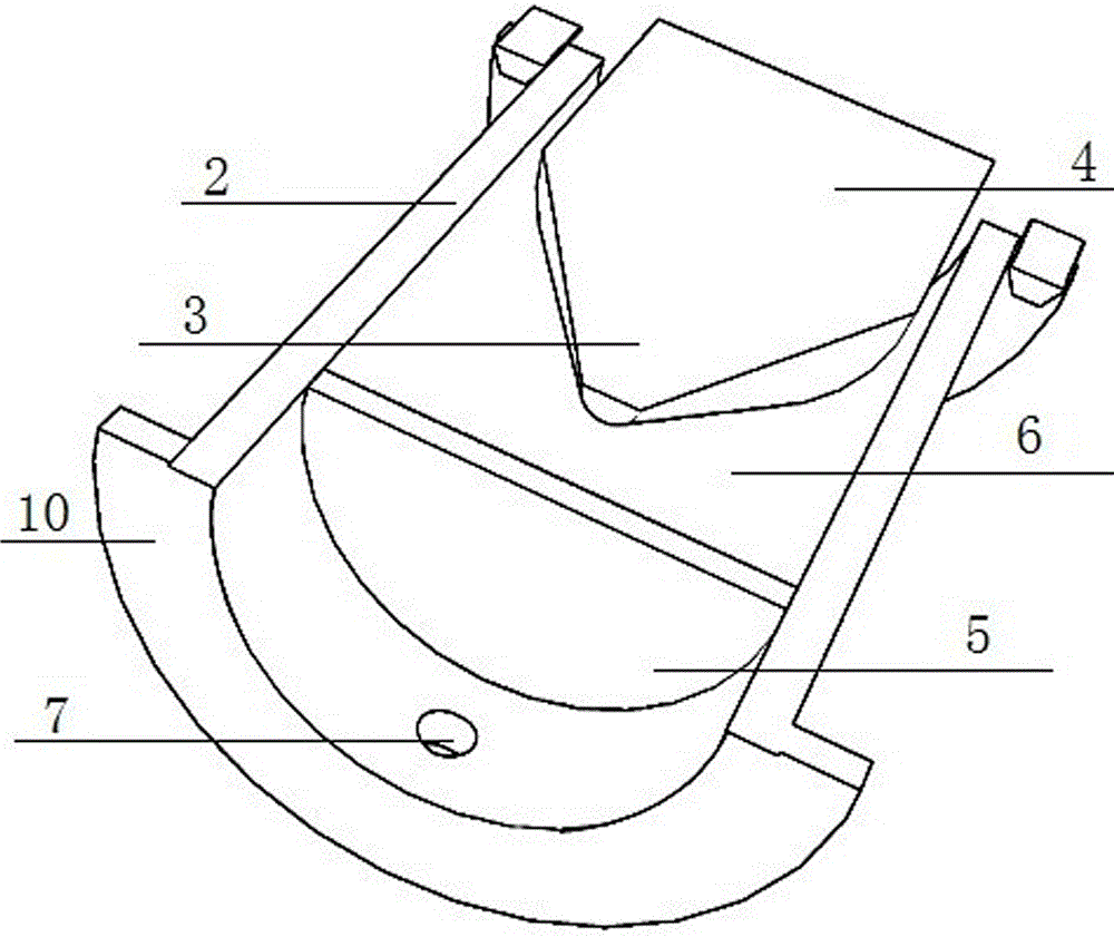
[0017] figure 1 , figure 2 The automobile collision buffer shown includes a hydraulic buffer mechanism fixed at the front end and / or rear end of the automobile chassis, and is characterized in that the hydraulic buffer mechanism includes at least three crushing buffer units 1 connected end to end in series; the The crushing buffer unit 1 includes a sleeve 2, and the sleeve 2 is slidably sealed with a crushing rod 4 with a tip 3; on the inner wall of the sleeve 1, a baffle 5 is sealed and fixed outside the tip 3 of the crushing rod 4; 2, between the baffle plate 5 and the crushing rod 4 is a liquid chamber 6 filled with liquid; the sleeve 2 outside the liquid chamber 6 is provided with a drainage hole 7; among at least three crushing buffer units 1, the The front end of the front crushing rod 9 of the crushing buffer unit 8 is exten...


PUM


Abstract

The invention discloses an automobile collision bumper, and relates to the technical field of automobiles. The automobile collision bumper comprises a hydraulic buffer mechanism fixed to the front end and / or the rear end of an automobile chassis, wherein the hydraulic buffer mechanism comprises at least three crush buffer units which are connected in series in an end-to-end mode, each crush buffer unit comprises a sleeve, each sleeve is provided with a crush rod with a pointed end in a sliding seal mode, a blocking sheet is fixed to the outer side of the pointed end of each crush rod in a sealing mode and is arranged on the inner wall of the corresponding sleeve, a liquid chamber filled with liquid is arranged between each blocking sheet and the corresponding crush rod and is arranged in the corresponding sleeve, and a drainage hole is formed in the portion, on the outer side of the corresponding liquid chamber, of each sleeve. The automobile collision bumper has the advantages that when the automobile collision bumper is installed on an automobile, due to the facts that the multiple levels of crush buffer units which are connected end to end are used, the blocking sheets are crushed step by step, and liquid is ejected out at a high speed, kinetic energy in the collision process of the automobile is converted, the collision time of the automobile can be prolonged, impact force is reduced, kinetic energy generated in the collision process can be absorbed, and the purpose that a human body and an automobile body are protected against damage at the same time is achieved.

Description

technical field [0001] The invention relates to the technical field of automobiles. Background technique [0002] At present, automobiles have already become a closely related means of transportation in people's lives because of their convenience and speed. But the tragedies of car crashes and fatalities caused by the accompanying traffic accidents also occur from time to time. And from the analysis of various accidents, it can be seen that the collision loss of the front and rear ends of the car is the most serious. In order to protect the safety of the occupants in the car as much as possible, the traditional design of the front and rear ends of the car follows the principle of "it is better to destroy the car than to die". At the same time, a bumper is also designed on the custom and rear of the car, and the C bumper is rigidly connected to the car body. When the car suffers a small collision force, the bumper can also play a role in protecting the car body to a certai...

Claims


Application Information

Patent Timeline
Patent Type & Authority Patents(China)
IPC IPC(8): B60R19/04
Inventor 赵义龙庞树宝
Owner WM MOTOR TECH GRP CO LTD
Why Eureka
Try Eureka