
Vehicle with distance monitoring device

A technology for monitoring devices and distances, which is applied in the field of vehicles and can solve problems such as lack of time

Inactive Publication Date: 2014-06-25
GM GLOBAL TECH OPERATIONS LLC
View PDF5 Cites 11 Cited by
  • Summary
  • Abstract
  • Description
  • Claims
  • Application Information

AI Technical Summary

Problems solved by technology

[0003] This parking aid is generally switched off when the vehicle is driving at normal cruising speed, because at cruising speed the driver must be aware in advance that there are no obstacles in the space monitored by the parking aid, however When in fact an obstacle is present and detected in the monitored space, the time left between detection and collision to take measures to avoid collision is insufficient

Method used


Image

  • Vehicle with distance monitoring device

Examples


Embodiment Construction

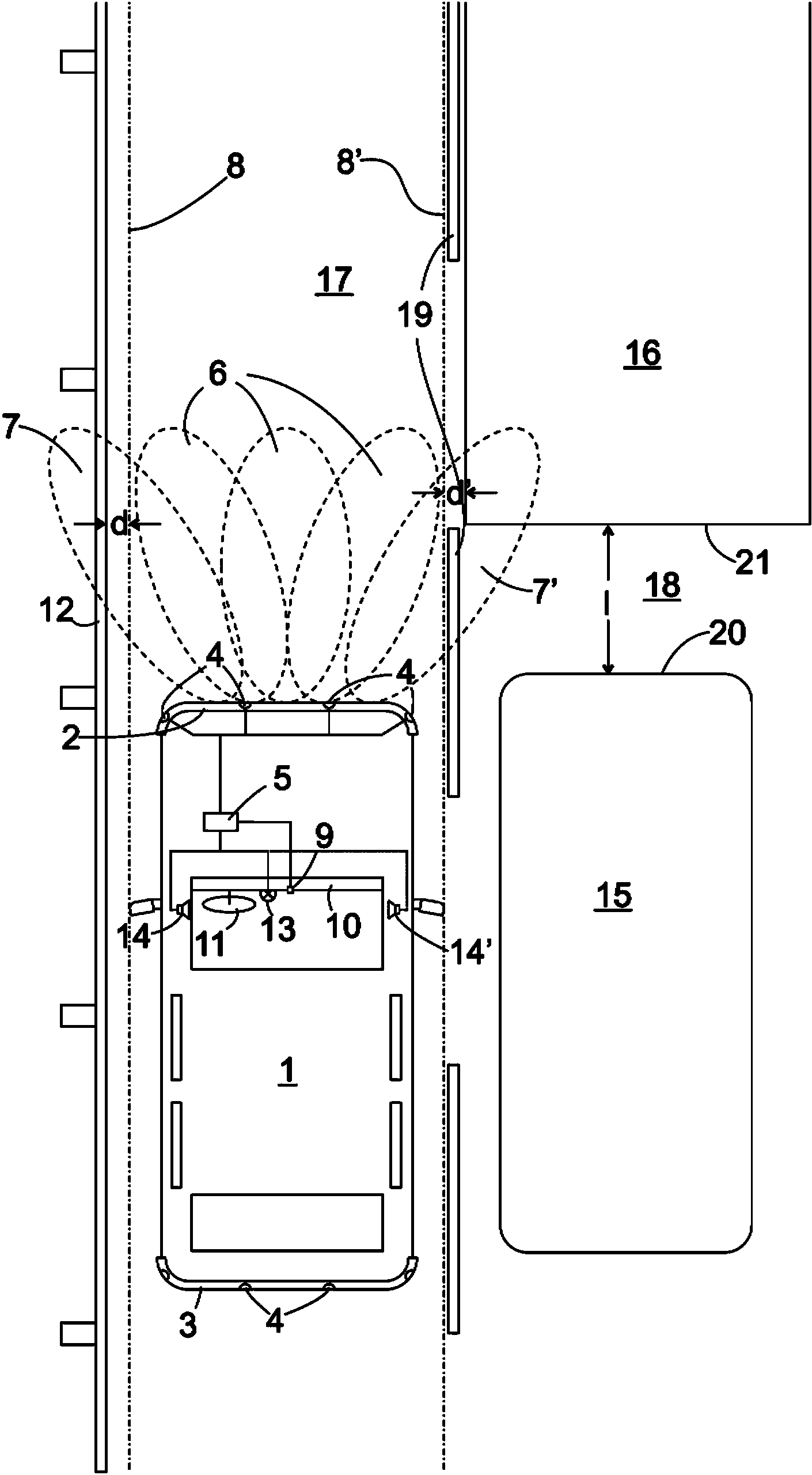
[0017] figure 1 The vehicle 1 shown has a plurality of ultrasonic transceiver units 4 on the front bumper 2 and rear bumper 3 , here four ultrasonic transceiver units per bumper, which transmit ultrasonic waves that are correlated with each other. , and capture echoes reflected by ultrasonic waves from the surrounding environment. The direction of ultrasonic emission or the direction of the best received reflected wave is determined by the directional characteristic of each transceiver unit 4 and the phase difference between the ultrasonic waves emitted by different units 4 or by a phase shift, and the received echo of unit 4 The wave signals are superimposed with said phase shift. The given sets of phase shifts thus each correspond to a detection zone 6 , 7 or 7 ′ in which existing obstacles are detected by using these sets. By switching the electronic control unit 5 between different phase shift groups, the control unit 5 can detect the presence of obstacles in a plurality...


PUM


Abstract

A vehicle has a distance monitoring device (4,5), which can be switched between a first operating mode for detecting the distance (1) to an obstacle located in travelling direction and a second operating mode for measuring a distance (d) transversely to the travelling direction to an obstacle (12) and outputting a signal in real time that is representative of the measured distance (d).

Description

technical field [0001] The invention relates to a vehicle with a distance monitoring device for detecting the distance to an obstacle or between two obstacles. Background technique [0002] Distance monitoring devices for monitoring the distance to obstacles in front of the vehicle in the forward and reverse direction of the vehicle are known and widely used as so-called parking aids. An optical and / or acoustic signal representing the measured distance is transmitted by the distance monitoring device so that the driver of the vehicle can approach an adjacent parking space more closely when adjusting the vehicle into a parking space than by visually alone the front and rear obstacles without risk of collision. Such distance monitoring devices usually comprise a plurality of ultrasonic transceiver units distributed along the front and rear bumpers of the vehicle. The echo signals reflected on obstacles and captured by the transceiver unit are superimposed on each other with ...

Claims


Application Information

Patent Timeline
Patent Type & Authority Applications(China)
IPC IPC(8): B60W30/08B60W30/06
CPCG08G1/168G08G1/167B60W30/06B60W30/08B60W2554/00
Inventor W.费奇
Owner GM GLOBAL TECH OPERATIONS LLC
Learn More