
Full jacket helical conveyor centrifuge with direct drive

a conveyor centrifuge and helical technology, which is applied in the direction of centrifuges, rotary centrifuges, etc., can solve the problems of high temperature at the belts and pulleys, is not suitable for larger centrifuges, and is often relatively loud,

Inactive Publication Date: 2006-08-17
WESTFALIA SEPARATOR AG
View PDF6 Cites 8 Cited by
  • Summary
  • Abstract
  • Description
  • Claims
  • Application Information

AI Technical Summary

Benefits of technology

[0011] According to the present disclosure, a belt drive for the drum can be eliminated. Instead, an electromagnetic gearless direct drive is used for the drum, which direct drive has a compact construction while the torque is high and is easily controllable in a low-noise manner. As a result, a safety advantage is also obtained because the drum can be braked particularly rapidly by the direct drive.
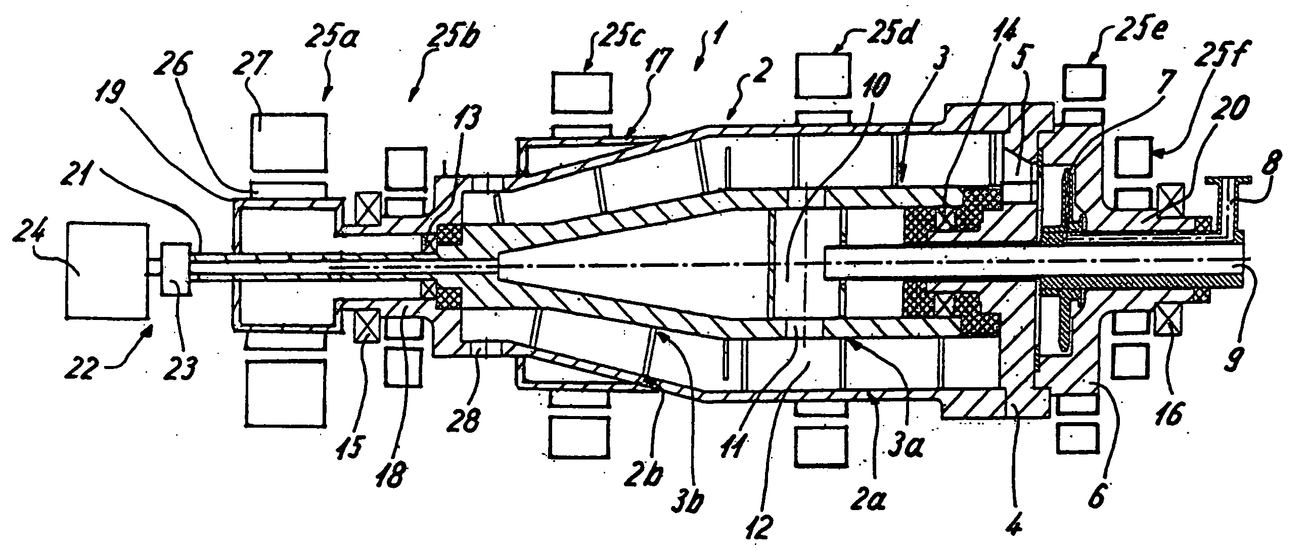
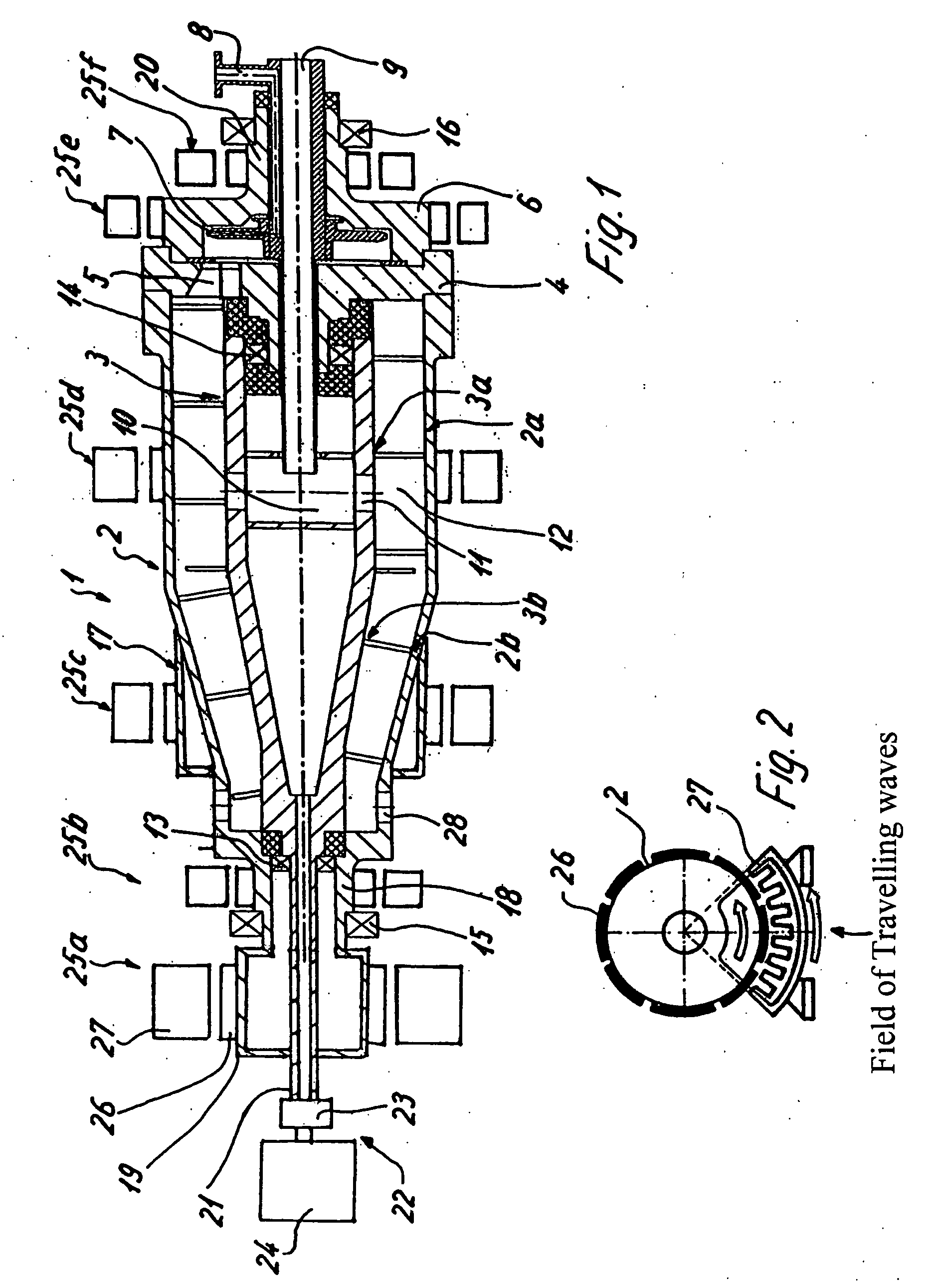
[0020] The present disclosure addresses a full-jacket helical conveyor centrifuge with a rotatably disposed metallic drum and a rotatable helical conveyor as well as a drive device for the drum and a drive device for the helical conveyor. At least the drive device for the helical conveyor has at least one electromechanical direct drive whose primary or secondary elements are arranged directly at or on a part non-rotatably connected with the helical conveyor, and whose corresponding secondary or primary elements are arranged without contact at a distance outside this part. A propulsion force being generated without gears by an electromagnetic field of travelling waves advances around the part non-rotatably connected with the helical conveyor. In this manner, a gearing between the drum and the helical conveyor could even be eliminated, so that the two elements can be controlled completely independently of one another. In this case, it may be advantageous to further develop both drives, that is, the drive for the drum and that for the helical conveyor, as a direct drive.

Problems solved by technology

For driving the drum, a belt drive is generally used which has been successful in practice but which requires a relatively large amount of space and therefore, because of frictional heat in the event of a belt slip, generates high temperature at the belts and the pulleys and is also often relatively loud.
Furthermore, from European Patent Document EP 0 930 099 B1, an electromagnetic transmission for driving a laboratory centrifuge is known which is connected behind an electric motor but which is not suitable for larger centrifuges, such as full-jacket helical conveyer centrifuges.
In contrast, a use on a full-jacket helical conveyor centrifuge has so far not been considered, probably because this type of centrifuge always also requires a drive for the helical conveyor and because an excessive heating of the product by way of the drum was also feared.

Method used


Image

  • Full jacket helical conveyor centrifuge with direct drive
  • Full jacket helical conveyor centrifuge with direct drive

Examples


Embodiment Construction

[0027]FIG. 1 illustrates a full-jacket helical conveyor centrifuge 1 with a rotatably disposed drum 2 and a rotatably disposed helical conveyor 3. The helical conveyor 3 has a differential or different rotational speed with respect to the drum 2 in an operation.

[0028] The drum 2, as well as the helical conveyor 3, each have a cylindrical section 2a, 3a with at least one outlet 5 for a liquid phase as well as a tapering, for example, conical section 2b, 3b adjoining on one side and having an outlet 28 for a solids phase.

[0029] On its cylindrical end, the drum 2 is closed off by a drum lid 4 which has the outlet 5 for the liquid phase, behind which, as an example, a chamber 6 is connected which has a centripetal pump 7 stationary in the operation and, in turn, followed by a discharge 8. Outlet 5 can also be followed by a baffle plate or directly by a discharge (not shown).

[0030] An inflow pipe 9 leads axially through the helical conveyor 3 or the helical conveyor body from the cyli...


PUM


Abstract

A full-jacket helical conveyor centrifuge including a rotatably disposed drum and a drive device for the drum. The drive device for the drum includes at least one electromechanical direct drive having secondary elements arranged on the outer periphery of the drum or on the outer periphery of a part non-rotatably connected with the drum. Primary elements are arranged radially outside the secondary elements at a distance from the secondary elements and without contact. A propulsion force is generated by an electromagnetic field of travelling waves.

Description

BACKGROUND AND SUMMARY [0001] The present disclosure relates to a full-jacket helical conveyor centrifuge including a rotatably disposed, metallic drum with a horizontal axis of rotation. Also included is at least one drive device for the drum. A helical conveyor is also included which is rotatably disposed at a differential rotational speed with respect to the rotational speed of the drum. The helical conveyor can be rotated by a gearing by the at least one drive device for the drum or by another device. [0002] It is known to drive centrifuges in many different manners. In the field of full-jacket helical conveyor centrifuges, it has caught on to equip the helical conveyor and the drum respectively with a driving device in order to be able to control these two elements separately from one another without any tie to a fixed transmission ratio. Such a state of the art is known from German Patent Document DE-A-2811887 or DE 1732887. [0003] For driving the drum, a belt drive is general...

Claims


Application Information

Patent Timeline
Patent Type & Authority Applications(United States)
IPC IPC(8): B04B1/20B04B9/04
CPCB04B1/2016B04B9/04
Inventor BEYER, HANS-JOACHIM
Owner WESTFALIA SEPARATOR AG
Learn More