
Method for draining accumulated floor water during super high-rise building construction, and apparatus thereof

A construction and super-high-rise technology, applied in water supply installations, buildings, and indoor sanitation pipeline installations, etc., can solve problems such as difficult control of accumulated water, unfavorable on-site civilized construction, and the impact of pedestrians and vehicles on the construction workers below, so as to reduce drainage cost effect

Active Publication Date: 2014-06-25
CCFED THE FIRST CONSTR & ENG
View PDF5 Cites 5 Cited by
  • Summary
  • Abstract
  • Description
  • Claims
  • Application Information

AI Technical Summary

Problems solved by technology

[0002] During the construction of super high-rise buildings, water will accumulate in the floors where the curtain walls are not installed due to factors such as rainfall. To solve this problem, the general method is to use artificial drainage. Directly use the bucket truck to dump the accumulated water to the outside of the floor. Since super high-rise buildings are generally located in urban areas and the construction site is small, the accumulated water poured out is difficult to control, and it is easy to affect the construction workers below, passing pedestrians and vehicles. Conducive to civilized construction on site
Moreover, a large amount of manpower is required for each drainage, which increases the construction cost.

Method used


Image

  • Method for draining accumulated floor water during super high-rise building construction, and apparatus thereof
  • Method for draining accumulated floor water during super high-rise building construction, and apparatus thereof

Examples


Embodiment Construction

[0019] The present invention will be further described in detail below in conjunction with the accompanying drawings, but not as any limitation to the present invention.

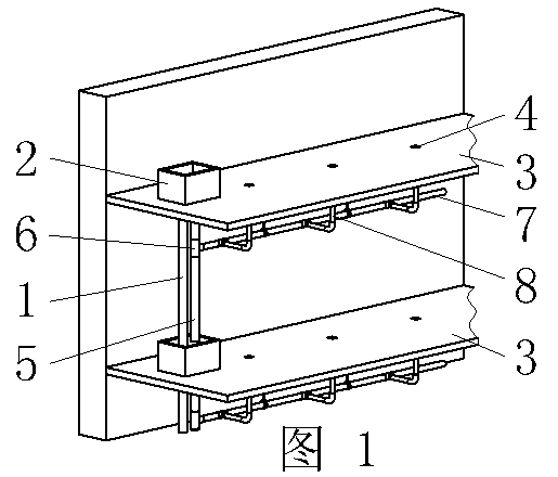
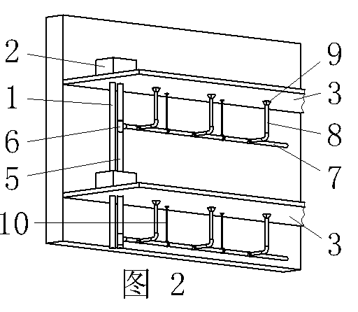
[0020] Drainage methods for floor water during construction of super high-rise buildings, such as figure 1 and figure 2 shown. The method is to build pools at the nozzles of the construction water supply pipes on each floor, and the height of the pools can be between 200-500mm to prevent water from leaking from the pipelines and flowing to the floors. At the bottom of the pool, there is a drainage riser leading to the pool on the lower floor, through which the water leaked from the water supply pipe is discharged layer by layer to the drainage ditch on the bottom floor; a set of floor drains are arranged at intervals on the edge of the floor of each floor, and the floor drain and the floor The horizontal drainage pipe below is connected, and the horizontal drainage pipe is connected to the vertical draina...


PUM

PropertyMeasurementUnit
Diameteraaaaaaaaaa
Diameteraaaaaaaaaa
Diameteraaaaaaaaaa

Abstract

The invention discloses a method for draining accumulated floor water during super high-rise building construction, and an apparatus thereof. The method comprises the following steps: building a water pool at the mouth of a construction water feeding pipe of each of floors, arranging a water draining standpipe connected with a water pool on a lower layer floor at the bottom of the water pool, and draining water leaked by the feeding pipes to a bottom waterway through the water drainage ditch layer by layer; setting a group of floor drain at the edges of floor slabs of each of the floor in an interval manner, connecting the floor drain with a water draining flat pipe below the floor slab, and connecting the water draining flat pipe with the water draining standpipe; and draining accumulated water in the construction process or rainwater to the bottom water drainage ditch through the floor drain layer by layer. Accumulated water generated by the floor during the super high-rise building construction or generated due to rain fall can be timely and orderly discharged from a construction site through the method and the apparatus without overturning the accumulated water out of the floor by directly utilizing a trolley through manpower drainage. The method and the apparatus have no influences on below construction workers, passing pedestrians and passing vehicles, are in favor of the onsite civilized construction, and can reduce the drainage cost.

Description

technical field [0001] The invention relates to a method and a device for draining water accumulated on a floor during super high-rise building construction, and belongs to the technical field of building construction drainage. Background technique [0002] During the construction of super high-rise buildings, there will be water accumulation in the floors where the curtain walls are not installed due to factors such as rainfall. Buildings are generally located in urban areas. The construction site is small, and the accumulated water poured out is difficult to control. It is easy to affect the construction workers below, passing pedestrians and vehicles, and is not conducive to civilized construction on site. Moreover, a large amount of manpower needs to be invested in each drainage, which increases the construction cost. Contents of the invention [0003] The object of the present invention is to provide a method and device for draining water accumulated on a floor durin...

Claims


Application Information

Patent Timeline
IPC IPC(8): E03C1/12E03C1/122
Inventor 袁茂生曾平谢翔王皓明睿
Owner CCFED THE FIRST CONSTR & ENG
Learn More