Water spraying cooling system of piston reciprocating internal combustion engine

A water spray system and piston technology, which is applied in the cooling of engines, internal combustion piston engines, combustion engines, etc., can solve the problems of fuel thermal efficiency loss, loss, low temperature pollutants, etc.

Inactive Publication Date: 2014-06-25
肖光宇
View PDF7 Cites 12 Cited by
  • Summary
  • Abstract
  • Description
  • Claims
  • Application Information

AI Technical Summary

Problems solved by technology

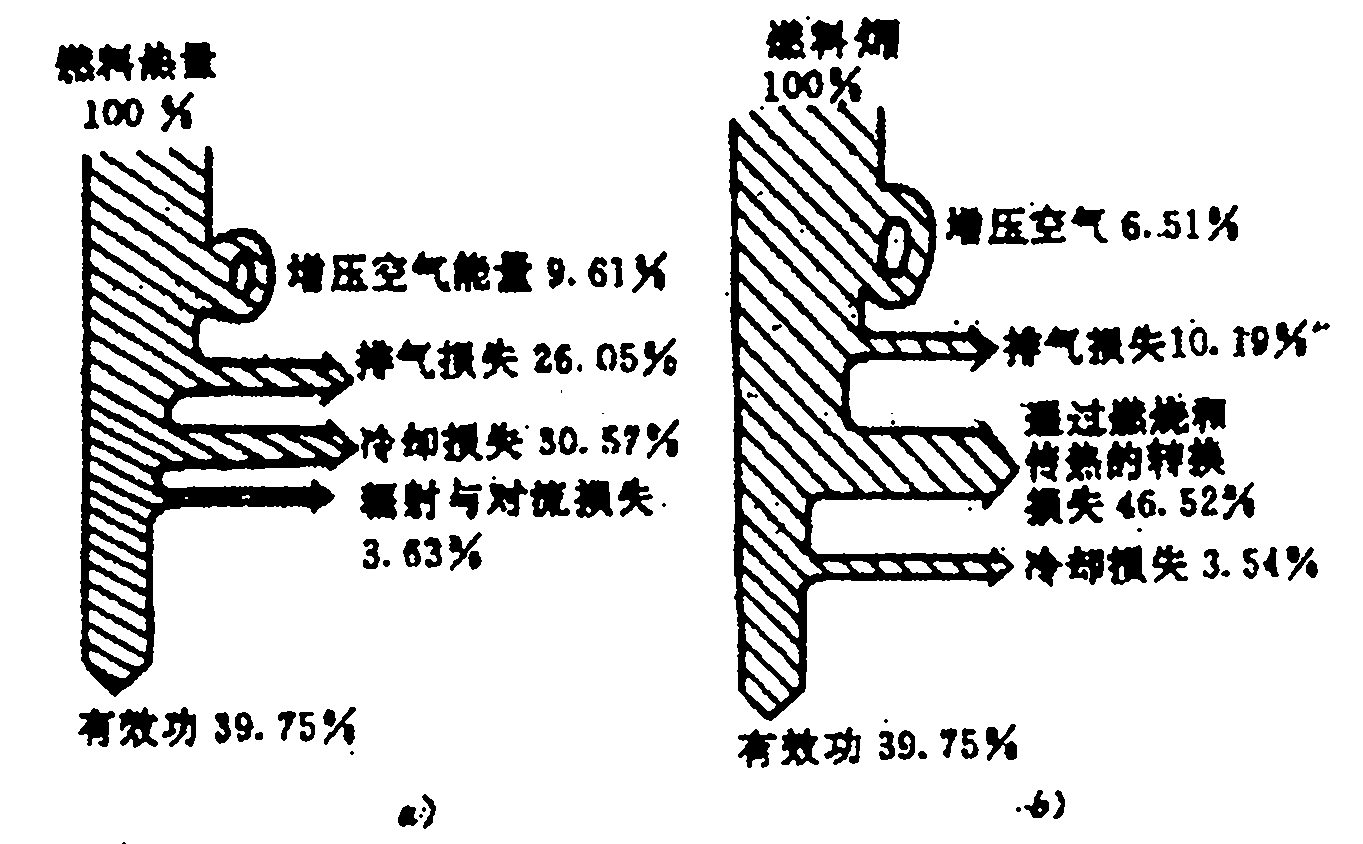
[0036] The "top-mounted secondary engine water spray system" can be positioned (the pump nozzle is placed on the top surface of the combustion chamber in the engine cylinder where the heat load is severe), and under the traction of the newly invented control system, it can be adjusted according to the engine working conditions The work of pumping and spraying water into the engine cylinder is carried out at a fixed timing, quantitative and constant rate; the "intercooled compression water spray system in the pressurized cylinder" can also be pumped and sprayed at a fixed time, quantitative and constant rate according to the change of the engine working condition. The work of the water liquid overcomes the defects of the existing traditional cooling method in terms of the cooling method; however, using the existing water liquid to absorb the heat of the fuel in the cylinder eliminates the high-temperature pollutant NO X The water injection parameters are formulated based on the concept of generation and heat load hazards. The water injection scheme formed will cause the loss of fuel "exergy" value (working ability) due to excessive cooling in the engine cylinder, resulting in the loss of fuel thermal efficiency. , and will also cause the formation of low-temperature pollutants

Method used


Image

  • Water spraying cooling system of piston reciprocating internal combustion engine
  • Water spraying cooling system of piston reciprocating internal combustion engine
  • Water spraying cooling system of piston reciprocating internal combustion engine

Examples


Embodiment Construction

[0083] A water injection cooling system for a piston reciprocating internal combustion engine of the present invention will be described in detail below in conjunction with the accompanying drawings for specific implementations of the present invention.

[0084] Announced in the invention patent "ZL200710193940.7 'a tappet and the combined mechanism and control system of the tappet'": described in claim 2 and claim 6, in the newly invented overhead integrated control system (instructions [ [0021] The specific method is recorded) [note: the control system has proposed a divisional application, application number 201110283190.9, name 'a kind of piston reciprocating internal combustion engine overhead integrated control system'] traction, synchronously with the change of the engine working conditions in their own The "top-mounted secondary engine in-cylinder water spray system" and the "supercharged in-cylinder intercooling compression water spray system" constitute a water spray ...


PUM


Abstract

The invention discloses a water spraying cooling system of a piston reciprocating internal combustion engine. The water spraying cooling system has the advantages that the structure and working process of an engine, the features of combustion of hybrid gas in an engine cylinder are utilized, and physical change after in-cylinder mixing after water is accurately sprayed to an inner pump of the engine cylinder in a constant-region, fixed-time, quantitative and constant-speed manner; aiming at temperature environments generating pollutants such as NO, HC and CO and a target of basically causing no 'exergy' value (acting capacity) loss of fuel in the engine cylinder, water spraying technological means and the evaluation concept of adopted water spraying parameters are determined, the system is operated under the newly-defined constant-region, fixed-time, quantitative and constant-speed working parameters, generation of various inefficiency combustion pollutants in the engine cylinder is eliminated, and about 30% of fuel heat efficiency loss caused by the existing cooling manners is avoided.

Description

technical field [0001] The invention belongs to an internal combustion engine, in particular to a cooling technology for a piston reciprocating internal combustion engine. Background technique [0002] The existing conventional internal combustion engine cooling technology scheme has caused about 30% loss of fuel thermal efficiency and a large amount of bad pollutants and carbon dioxide emissions to the atmosphere. The large amount of thermal efficiency loss is negated in essence, which has led to taking it for granted and turning a blind eye for a long time. This defect and insufficiency, compared with the conventional internal combustion engine, which is the most widely used and used in the largest amount, and its fuel consumption accounts for about 80% of the global fuel consumption, especially in the face of international disputes caused by the shortage of fuel resources today, a large amount of bad combustion pollution The emission of pollutants and carbon dioxide into...

Claims


Application Information

Patent Timeline
Patent Type & Authority Applications(China)
IPC IPC(8): F01P9/02F02B29/04
CPCY02T10/12
Inventor 肖光宇
Owner 肖光宇
Why Eureka
Try Eureka