Quantified liquid supply device
A quantitative liquid supply and liquid intake technology, applied in the direction of quantitative devices, engine components, engine lubrication, etc., can solve the torque imbalance between the rotation of the stator and the rotor, the measurement of the quantitative liquid supply device is not too accurate, and the liquid supply pipeline is easy to block and other issues, to achieve the effect of expanding the universality, shortening the cycle time, and improving the safety
- Summary
- Abstract
- Description
- Claims
- Application Information
AI Technical Summary
Problems solved by technology
Method used
Image
Examples
Embodiment 1
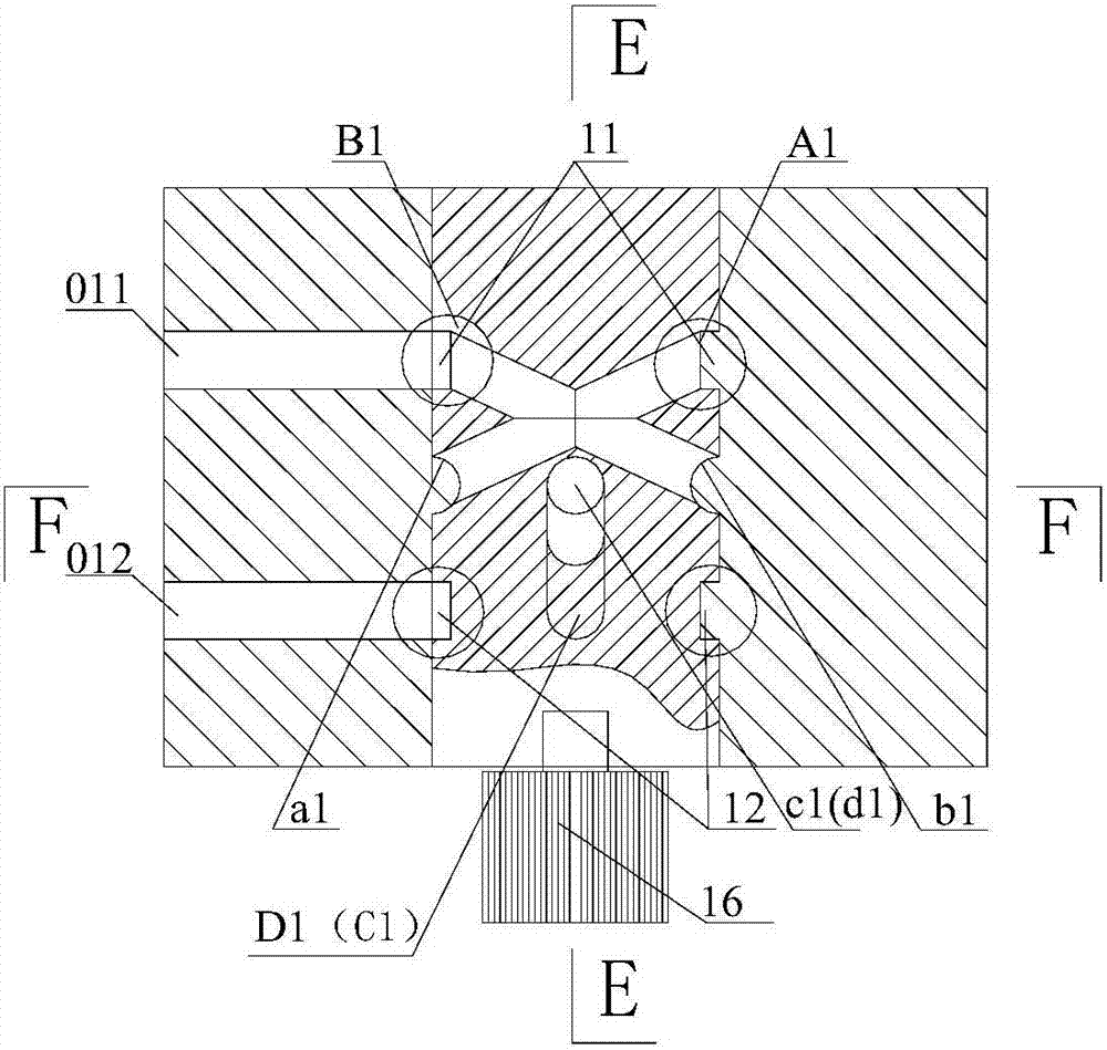
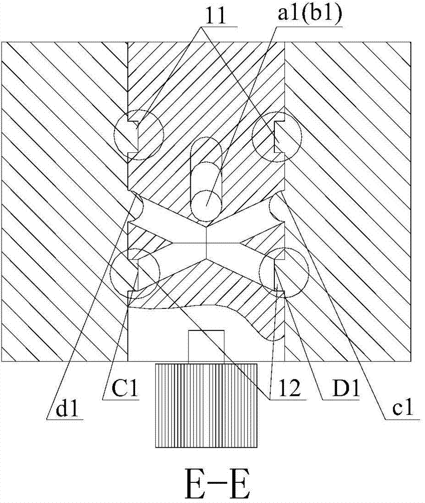
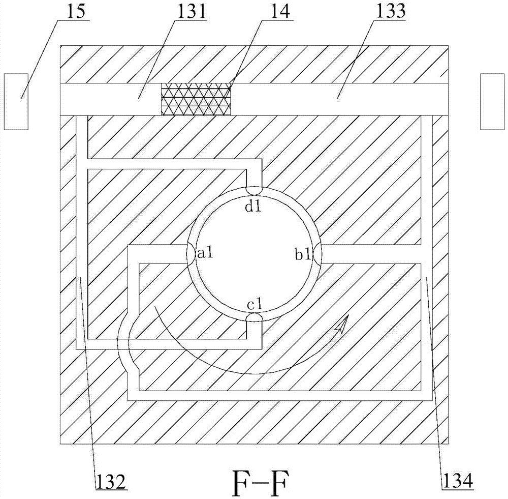
[0034] like Figures 1 to 9 As shown, the quantitative liquid supply device of this embodiment includes a rotating core and a stator sleeved on the rotating core, and the stator and the outer wall of the rotating core are liquid-tightly matched.
[0035] The rotating core includes a liquid circuit mechanism, and the liquid circuit mechanism includes a liquid inlet unit and a liquid outlet unit.
[0036] The liquid inlet unit includes a single liquid inlet structure, wherein the single liquid inlet structure includes a group of liquid inlet channels and a liquid inlet annular groove 11 arranged on the rotating core, and the liquid inlet channel is formed by the The rotating core is composed of two intersecting liquid inlet pipes, and the intersection point of the liquid inlet pipes is on the axis line of the rotating core, the liquid inlet annular groove is arranged around the axis line, and each of the The liquid inlet holes B1 and A1 of the liquid inlet pipe are arranged in ...
Embodiment 2
[0050] like Figures 10 to 15 As shown, the quantitative liquid supply device of this embodiment includes a rotating core and a stator sleeved on the rotating core, and the stator and the outer wall of the rotating core are liquid-tightly matched.
[0051] The rotating core includes a liquid circuit mechanism, and the liquid circuit mechanism includes a liquid inlet unit and a liquid outlet unit.
[0052] The liquid inlet unit includes a double liquid inlet structure, and the double liquid inlet structure includes two groups of liquid inlet channels symmetrically arranged on the rotor core and a liquid inlet annular groove 21, wherein the liquid inlet channels are composed of The rotating core is composed of at least two intersecting liquid inlet pipes, and the intersection point of the liquid inlet pipes is on the axis line of the rotating core, and the liquid inlet annular groove is arranged around the axis line , the liquid inlet holes A2 and B2 of each of the liquid inlet...
Embodiment 3
[0068] The quantitative liquid supply device of this embodiment has been partially changed on the basis of Embodiment 2. The change is that the liquid outlet unit of this embodiment includes a double liquid outlet structure, and the double liquid outlet structure includes symmetrically arranged Two sets of liquid inlet passages and a liquid inlet annular groove on the rotor core, the liquid inlet passages are composed of two intersecting liquid inlet pipes on the rotor core, and the intersection point of the liquid inlet pipes is at On the axis of the rotating core, the liquid inlet annular groove is arranged around the axis, the liquid inlet holes of each of the liquid inlet pipes are arranged in the liquid inlet annular groove, and each of the liquid inlet channels The liquid outlet holes are arranged on the outer wall of the rotating core, wherein the liquid inlet holes of the two liquid inlet pipes corresponding to the two groups of liquid inlet channels in the double liqui...
PUM
 Abstract
Description
Claims
Application Information
 - R&D
- Intellectual Property
- Life Sciences
- Materials
- Tech Scout
- Unparalleled Data Quality
- Higher Quality Content
- 60% Fewer Hallucinations
Browse by: Latest US Patents, China's latest patents, Technical Efficacy Thesaurus, Application Domain, Technology Topic, Popular Technical Reports.
© 2025 PatSnap. All rights reserved.Legal|Privacy policy|Modern Slavery Act Transparency Statement|Sitemap|About US| Contact US: help@patsnap.com


