Charge Cable Device

A charging cable and cable technology, applied in charging stations, coupling devices, control devices, etc., can solve problems such as unit expansion or limited flexibility

Inactive Publication Date: 2014-06-25
DENSO CORP
View PDF7 Cites 4 Cited by
  • Summary
  • Abstract
  • Description
  • Claims
  • Application Information

AI Technical Summary

Problems solved by technology

Therefore, the scalability or flexibility of the unit is very limited

Method used


Image

  • Charge Cable Device
  • Charge Cable Device
  • Charge Cable Device

Examples


no. 1 example

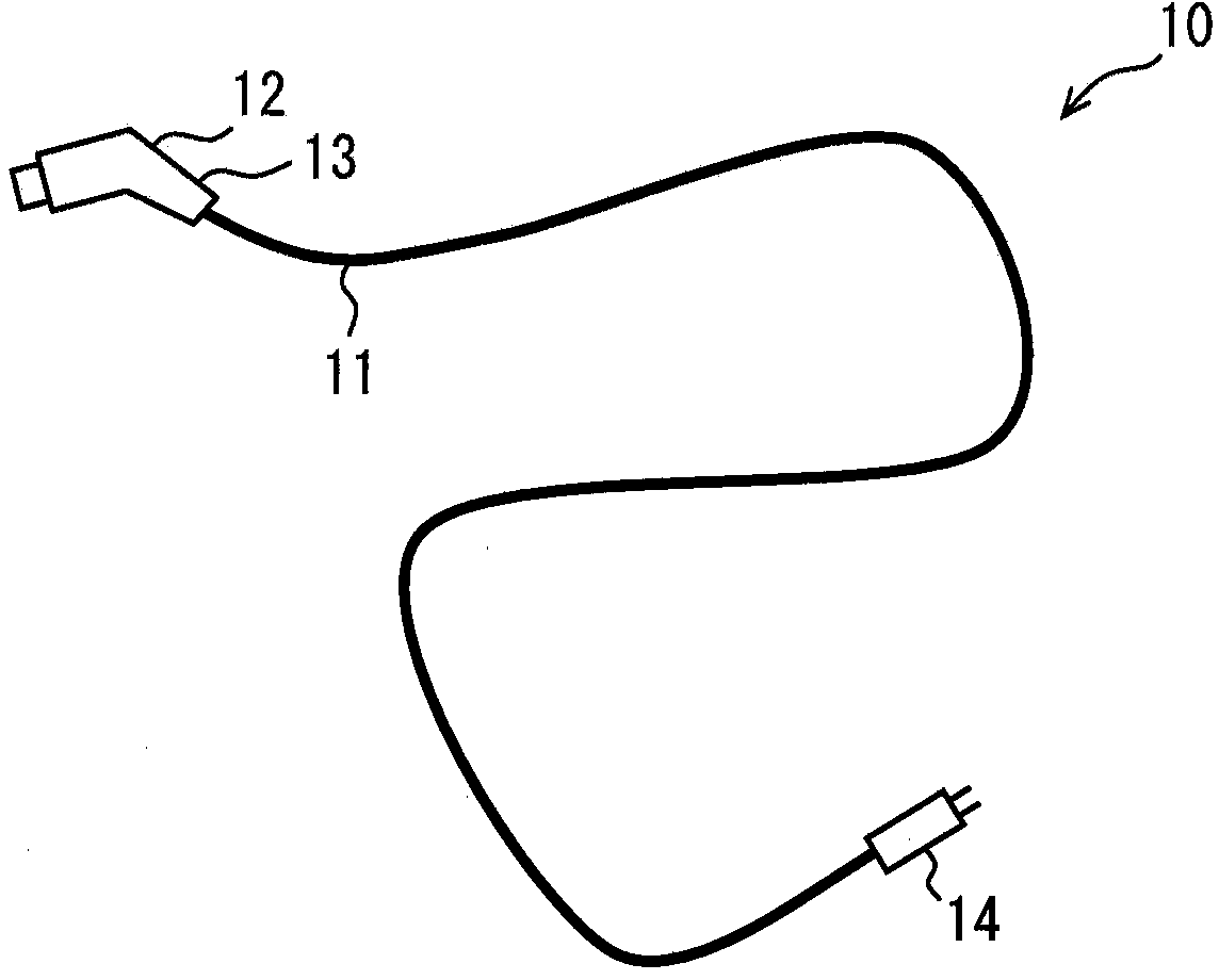
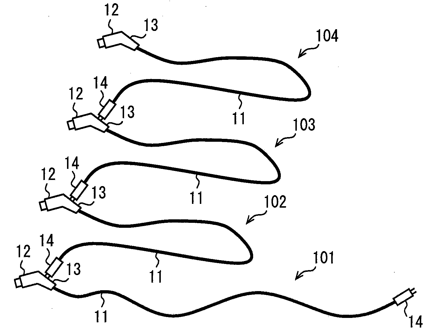
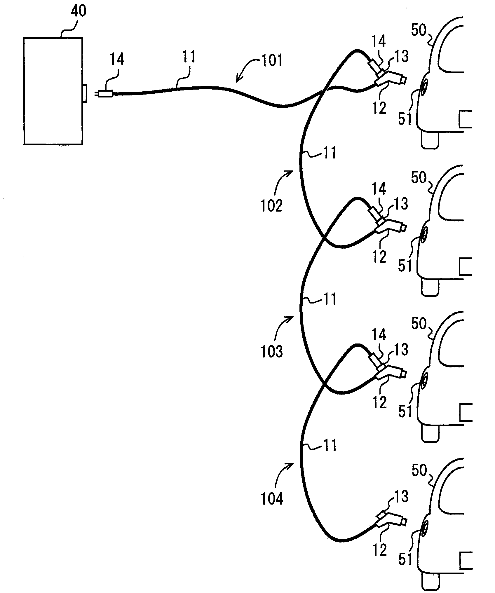
[0042] Refer to the following Figure 1-6 A charging cable device according to a first embodiment will be described. Such as image 3 As shown, when a battery mounted on a vehicle 50 is charged, the charging cable device 10 supplies electric power from a charging station as a power source to a vehicle 50 such as an electric vehicle and a plug-in hybrid vehicle, wherein the vehicle 50 includes a battery as a drive Power source motor. Such as figure 1 with figure 2 As shown, the charging cable device 10 includes a cable 11 connected to a charging station 40, a charging gun 12 arranged at the top end of the cable 11, and a connector (ie, a cable connector) to be connected to another charging cable device 10 13.

[0043] The cable 11 has a top end to which a charging gun 12 is connected and the other end to which a connector plug 14 is arranged. The connector plug 14 is electrically or mechanically separable from the charging station 40 and from the connector 13 of the furt...

no. 2 example

[0072] Next, refer to Figure 7 A charging cable device according to a second embodiment is explained. In the present embodiment, in the charging cable device 10A, the charging gun 12A and the connector 13A are separate bodies.

[0073] Such as Figure 7 As shown, the charging gun 12A and the connector 13A are formed separately. The connector 13A is provided at the middle of the cable 11 . Accordingly, the connector plug 14A of the other charging cable device 10A is connected to the connector 13A at the middle of the cable 11 provided on the connector plug side of the cable 11 as compared with the first embodiment.

[0074] In the first embodiment, the CCID is built into the charging gun 12, and the CCID controls the relays 26, 27 to be turned on and off. Alternatively, a CCID box as the connector 13A may be provided at the middle of the cable 11 . Further, a socket into which the connector plug 14A is inserted may be arranged in the case.

no. 3 example

[0076] Next, refer to Figure 8 A charging cable device according to a third embodiment is explained. In the present embodiment, a charging cable device 10B includes a charging gun 12B having a structure different from that of the first embodiment.

[0077] Such as Figure 8 As shown, the connector 13B incorporated into the charging gun 12B has such a connection structure 130 that the connector plug 14 of the other cable 11 is inserted into the connector 13B in an upward direction. In the state where the charging gun 12B is connected to the charging inlet 51 of the vehicle 50, as Figure 8 As shown, the connector plug 14 of the other cable 11 is inserted into the connector 13B in the direction from the lower side to the upper side. Further, the connector 13 includes a cover 131 for covering the outside of the connection structure 130 . The cover 131 extends from the connection structure 130 to the lower side. Therefore, when the connector plug 14 of another cable 11 is in...


PUM


Abstract

The present invention discloses a charge cable device. The charge cable device includes: a cable (11) having one end detachable from a power source (40) or another charge cable device and an electric power line (21) for supplying electricity to a vehicle from the electric power source or another charge cable device; a charge connector (12) on the other end of the cable (11) detachable from a charge inlet (51) of the vehicle; a cable connector (13) detachable from further another charge cable device to connect between further another charge cable device and the electric power line (21); and a controller (25). When the cable connector (13) is not attached to further another charge cable device, the controller (25) controls to supply electricity from the one end of the cable (11) to the charge connector (12). When the cable connector (13) is attached to further another charge cable device, the controller (25) controls an electric power supply amount of electricity to the charge connector (12) and to further another charge cable device.

Description

technical field [0001] The present disclosure relates to a charging cable device for supplying electric power from a charging power source to a vehicle. Background technique [0002] Conventionally, there is known a charging cable device having a cable extending from a charging power source such as a power supply station. A charging connector to be connected to the charging inlet of the vehicle is arranged on top of the cable. In general, a charging cable device is included for use in various parking positions even when the charging cable device charges various vehicles having charging inlets at different positions and when the vehicle is parked in various parking directions with respect to a power supply station (ie, a charging station). The long cable that can reach the charging inlet sufficiently even when in the position. [0003] However, the cable extending from the charging station is one. Therefore, if the charging station is charging multiple vehicles with electr...

Claims


Application Information

Patent Timeline
Patent Type & Authority Applications(China)
IPC IPC(8): H01R31/06H01R13/66
CPCB60D7/00B60L2240/70B60L2250/12Y02T90/16Y02T90/14Y04S30/14B60L53/16B60L53/65B60L53/18B60L53/305B60L53/67Y02T10/7072Y02T10/72Y02T90/12Y02T90/167Y02T10/70B60D99/00
Inventor 金森贵志栗本昌幸
Owner DENSO CORP
Why Eureka
Try Eureka