Hydrostatic linear actuator and device with hydrostatic linear actuator

A linear actuator and hydrostatic technology, applied in the direction of fluid pressure actuators, oil supply tank devices, engines, etc., to achieve the effect of minimizing the structural space

Active Publication Date: 2020-03-17
ROBERT BOSCH GMBH
View PDF15 Cites 0 Cited by
  • Summary
  • Abstract
  • Description
  • Claims
  • Application Information

AI Technical Summary

Problems solved by technology

[0005] A disadvantage of the last-mentioned actuator is its overall length, since the differential cylinder and the sump are arranged one behind the other in the working direction of the differential cylinder

Method used


Image

  • Hydrostatic linear actuator and device with hydrostatic linear actuator
  • Hydrostatic linear actuator and device with hydrostatic linear actuator
  • Hydrostatic linear actuator and device with hydrostatic linear actuator

Examples


Embodiment Construction

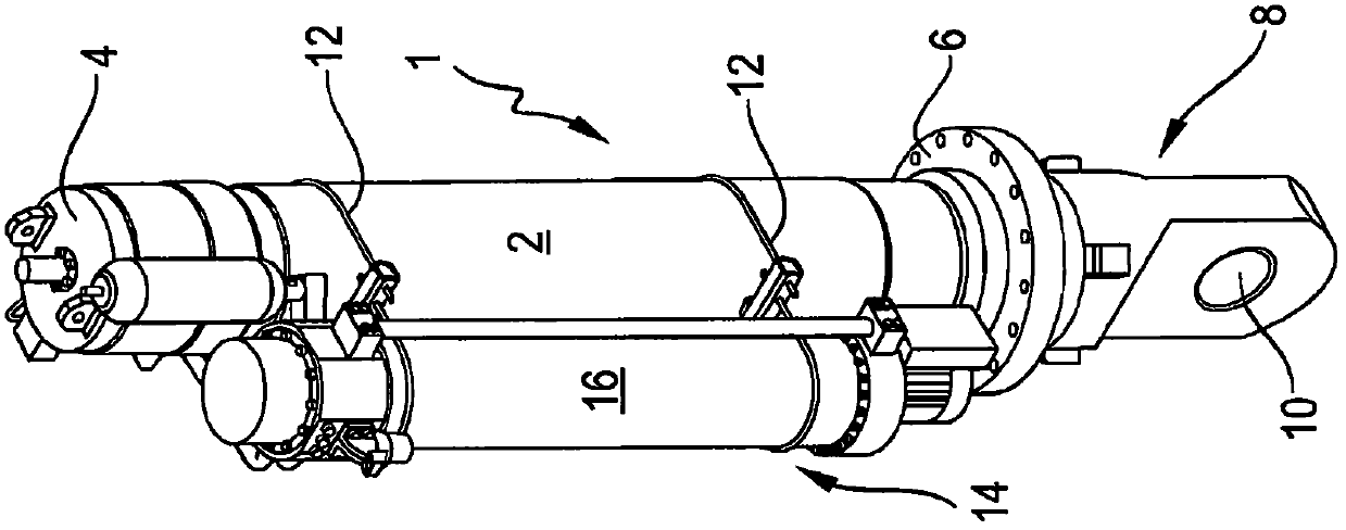
[0035] figure 1 An embodiment of an actuator according to the invention is shown. The actuator has a differential cylinder 1 in which the figure 1 A cylindrical cylinder tube 2 with a bottom-side closing plate 4 and a rod-side closing plate 6 is shown in FIG. The closure plate 6 on the piston rod side is closed (in figure 1 Not shown in ) the piston rod passes through, and the coupling element 8 with the eye 10 is fastened on its free end section.

[0036]The low-pressure accumulator 14 is fastened parallel to the cylinder tube 2 by means of two spaced apart, angled fastening means 12 , wherein the two fastening means 12 each enclose the cylinder tube of the differential cylinder 1 2 and the cylindrical pipe fitting 16 of the low pressure accumulator 14.

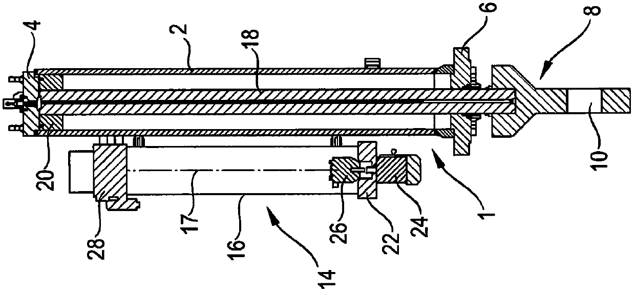
[0037] figure 2 A sectional view of this embodiment of the actuator according to the invention is shown. A piston rod 18 is shown inside the cylinder tube 2 , which rigidly connects the piston 20 of the differential c...


PUM


Abstract

A functionally and structurally compact hydrostatic actuator and a device having a plurality of such actuators are disclosed. The actuator according to the invention has a differential cylinder which determines the overall length of the actuator, since the pump, the electric motor and the low-pressure accumulator are arranged on the outer circumference of the cylinder tube of the differential cylinder edge and is fixed directly or indirectly on the outer perimeter.

Description

technical field [0001] The invention relates to a hydrostatic linear actuator with a differential cylinder and to a device with a plurality of such actuators. Background technique [0002] Hydrostatic linear actuators with cylinders, the piston rod of which can be moved in and out, are known from the prior art. If a mobile work machine, such as an excavator, requires several such actuators or cylinders, these are supplied by the same pump and via a corresponding metering orifice. The same pump is driven by the central motor of the mobile working machine, for example a diesel motor. In this design, hydraulic lines of considerable length are required to bridge the separation of the individual cylinders from the central pump. [0003] US 2010 / 0199565 A1 describes a hydrostatic linear actuator with a differential cylinder to which exactly one hydrostatic pump with a corresponding electric motor and exactly one storage tank are assigned. Thus, a functionally compact unit with ...

Claims


Application Information

Patent Timeline
Patent Type & Authority Patents(China)
IPC IPC(8): F03D7/02F01D7/00F03D7/04
CPCF03D7/0224F05B2260/76F05B2270/604Y02E10/72F15B1/26F15B15/18
Inventor L·卡斯帕斯C·罗林克S·伯伊彦C·唐克斯
Owner ROBERT BOSCH GMBH
Why Eureka
Try Eureka