Leakage detection and protection circuit with timing self-test function of discrete components
A discrete component and leakage detection technology, applied in the direction of emergency protection circuit devices, automatic disconnection emergency protection devices, electrical components, etc., can solve problems that require a relatively complicated judgment process and need to be perfected, to prevent instantaneous high voltage from damaging the circuit, Easy to use and safe effect
- Summary
- Abstract
- Description
- Claims
- Application Information
AI Technical Summary
Problems solved by technology
Method used
Image

Examples
Embodiment 1
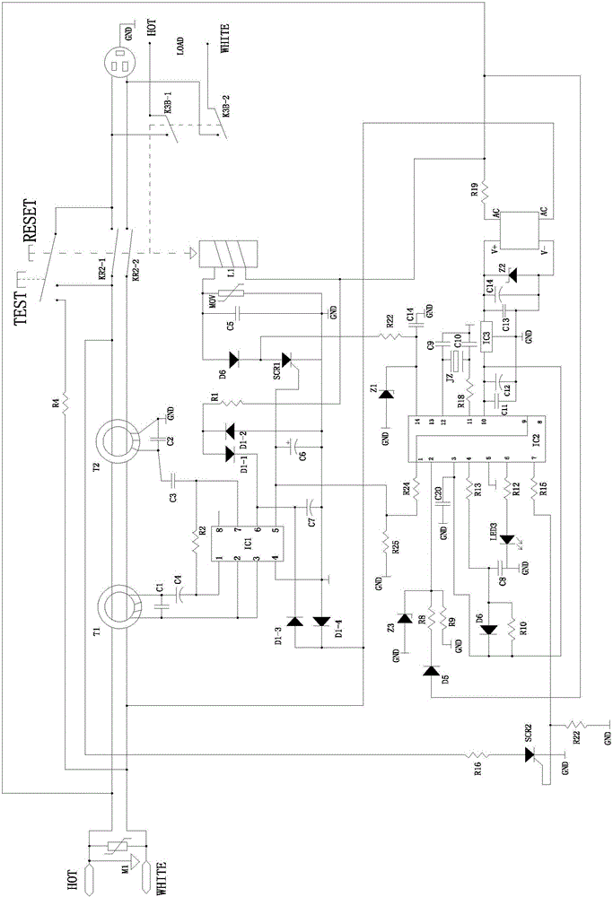
[0021] Reference figure 1 , The leakage detection and protection circuit with discrete component timing self-check function of this embodiment includes power input terminal, power user terminal, power output terminal, reset button, and main circuit switch (KR2-1, KR2-2) linked with the reset button ), dual induction coils (T1, T2) for detecting leakage current and low resistance faults, trip coil L1 that drives the built-in iron core through the action of a magnetic field and cooperates with the mechanical structure to make the reset button drive the main circuit switch to close / open. The thyristor SCR1 provided by the buckle coil, the control chip IC1 that controls the on-off of the thyristor through the detection results of the double induction coils, and the timing self-check circuit. The timing self-check circuit includes the self-check chip IC2 and the second thyristor SCR2; The trigger electrode of the SCR SCR1 is led to the drive pin of the control chip IC1 and to the A / D...
Embodiment 2
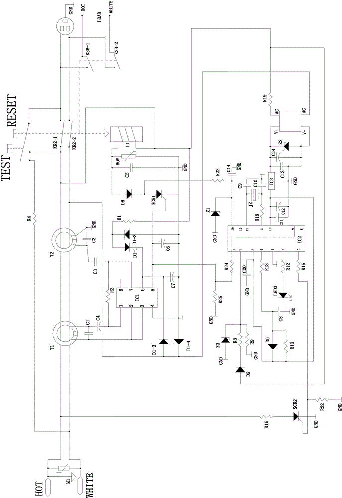
[0030] Reference figure 2 In this embodiment: the anode of the second thyristor SCR2 is connected to the live wire of the power input terminal that does not pass through the double induction coil, and the power terminal of the self-check chip IC2 is connected to the neutral end of the double induction coil to form a double induction coil. The loop. The structure of the normally open switch of this example is the same as that of the first embodiment.
Embodiment 3
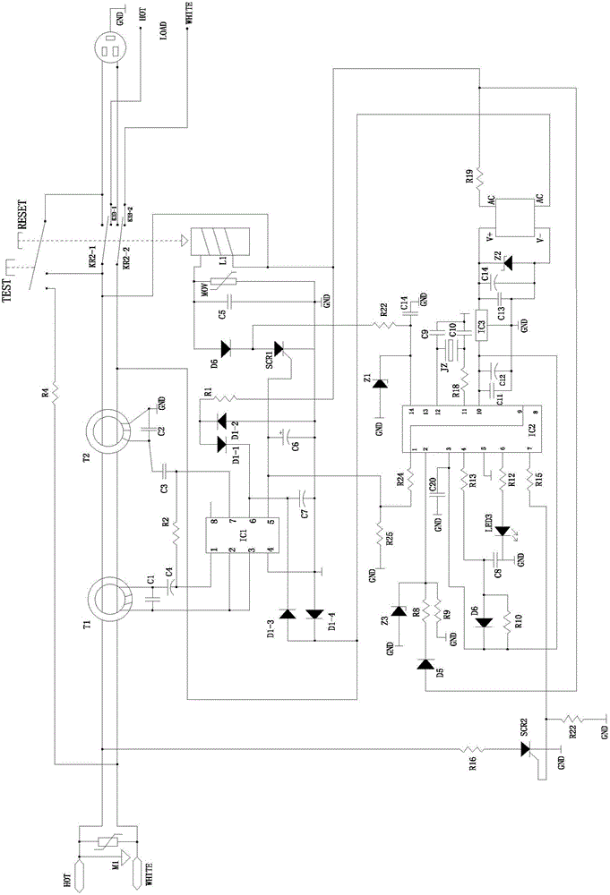
[0032] Reference image 3 The connection method of the second thyristor SCR2 of this embodiment is the same as that of the second embodiment. The connection method of the normally open switch (K3B-1, K3B-2) used for reverse wiring protection is different from that of the first embodiment. The middle normally open switch (K3B-1, K3B-2) includes a pair of moving contacts connected to the output terminal of the power supply. The pair of moving contacts are located below (or above) the moving contact rod of the main circuit switch. When the main circuit switch is closed, the normal The movable contact piece of the open switch (K3B-1, K3B-2), the movable contact rod of the main circuit switch and the static contact terminal of the main circuit switch are in contact and conduction.
PUM
 Abstract
Description
Claims
Application Information