Filler yarn bar

A technology of warp yarn and bar, applied in warp knitting, flat warp knitting machine, textile and paper making, etc., can solve problems such as unfavorable additional costs

Inactive Publication Date: 2014-06-25
RWTH AACHEN UNIVERSITY
View PDF7 Cites 0 Cited by
  • Summary
  • Abstract
  • Description
  • Claims
  • Application Information

AI Technical Summary

Problems solved by technology

[0009] In the state of the art, it has also become known during this period to provide an already knitted textile, such as the aforementioned multiaxial fabric, in a further process step for increasing the strength of the fabric or generally with local thickenings for increasing the strength of each textile to be knitted, which has hitherto been carried out according to the preceding knitting steps and thus entails disadvantageous additional costs

Method used


Image

  • Filler yarn bar
  • Filler yarn bar
  • Filler yarn bar

Examples


Embodiment Construction

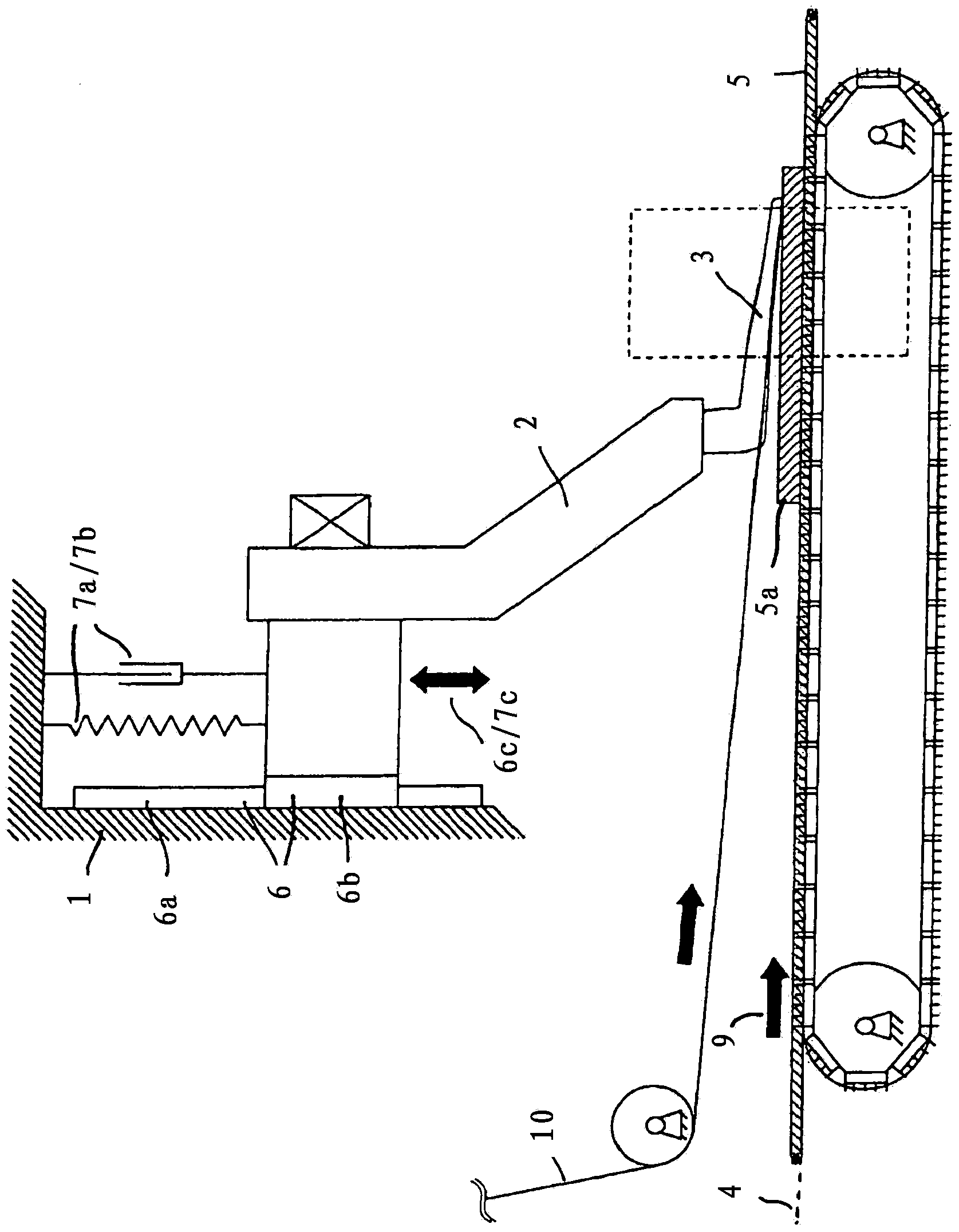
[0050] here figure 1 In particular, the remaining figures show a warp bar, which comprises a support element 1 that can be calibrated to be arranged in a warp knitting machine, on which a straight line in the structure shown schematically is fastened. Guide rail 6a of the bearing mechanism, in particular of the linear sliding bearing mechanism.

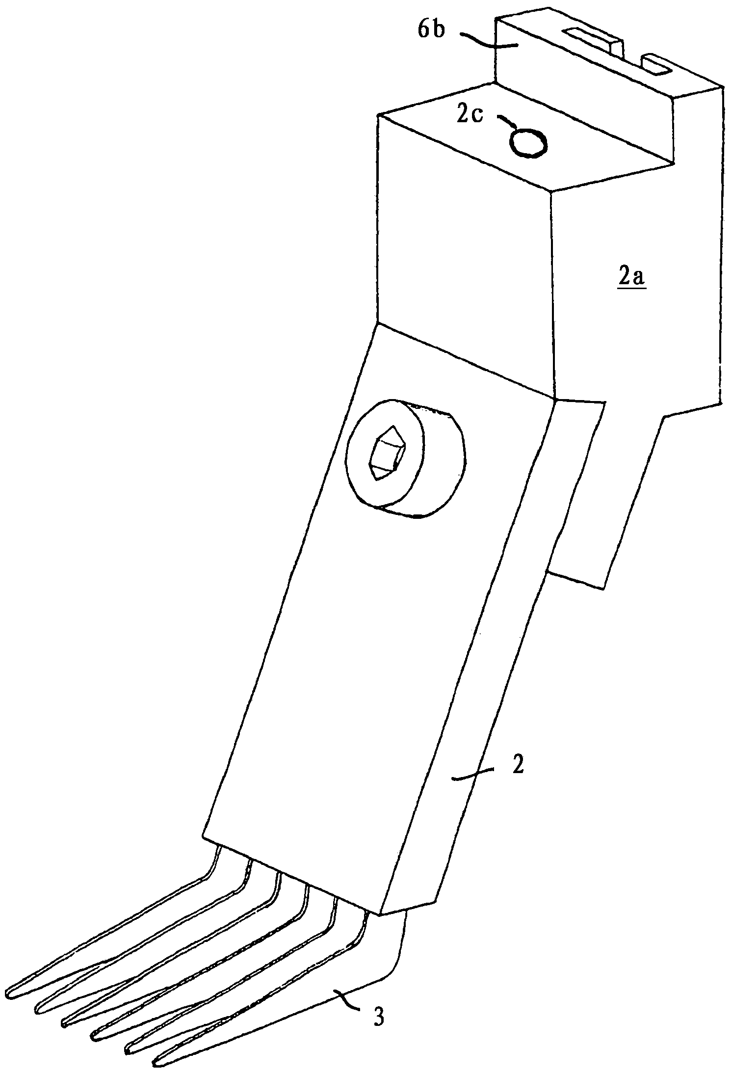
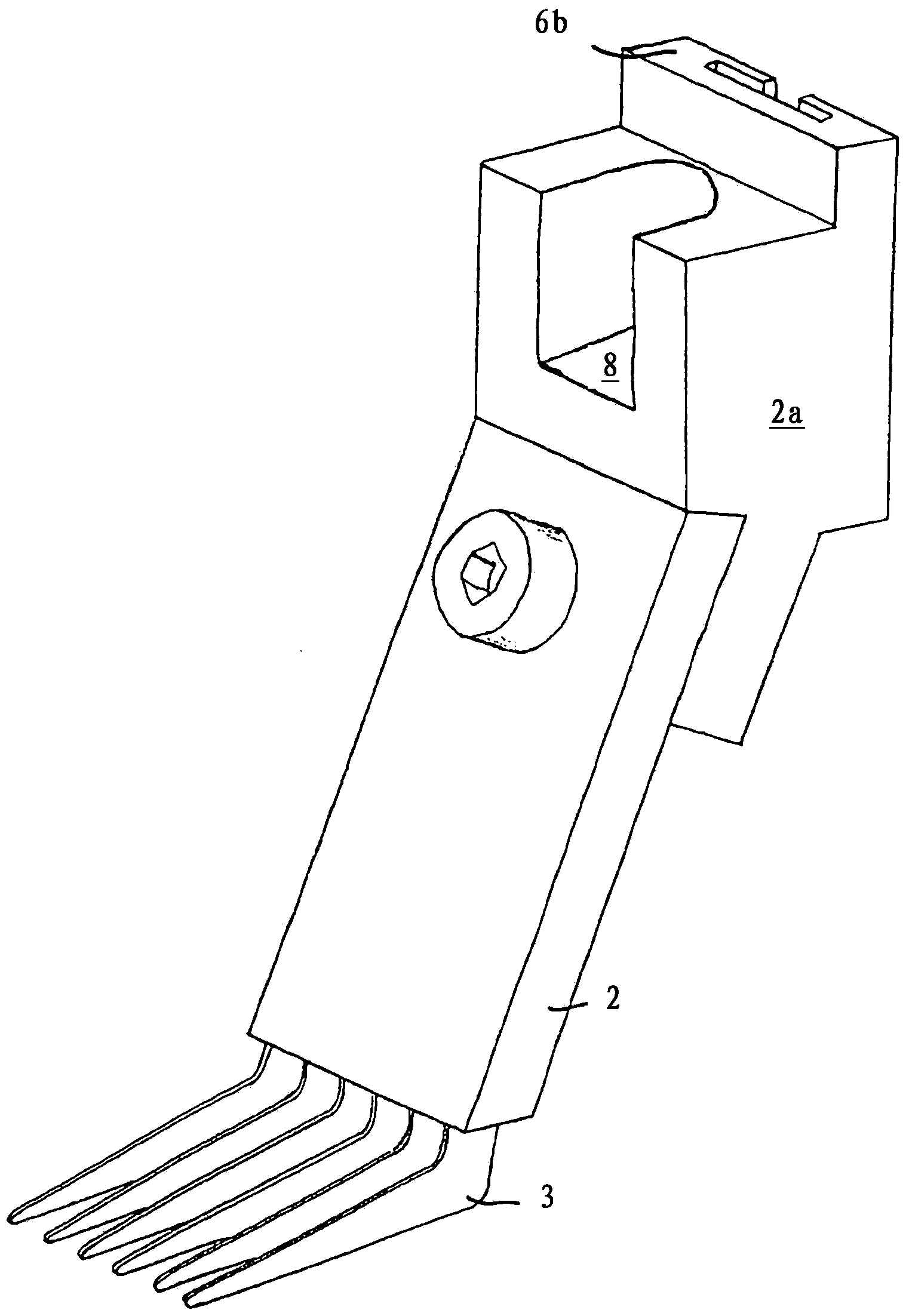
[0051] A guide carriage 6b can be moved in the vertical direction, that is to say here in a direction perpendicular to the conveying plane 4 of the warp knitting machine, on which guide carriage the warp bar bow is indirectly fastened here via the bow section support 2a. Segment 2, which has a warp thread sinker 3 arranged on it at the bottom, which is a segment of the warp bar segment.

[0052] Because the warp bar segment 2 is arranged on the support element 1 by the linear support mechanism 6, the underside of the warp sinker lying on the surface of the textile 5 to be knitted can be compared with the thickness jump in the textile...


PUM


Abstract

The invention relates to a filler yarn bar of a warp knitting machine, which comprises at least one carrier element (1), on which a plurality of filler yarn bar segments (2) with filler yarn cards (3) are arranged, wherein at least some of the total number of filler yarn bar segments (2), preferably all of the filler yarn bar segments (2), are seated on the carrier element (1) movably relative to the carrier element (1), particularly in such a manner that the distance between the filler yarn cards (3) and a conveyance level (4) of a warp knitting machine can be changed by such movement.

Description

technical field [0001] The invention relates to a warp thread bar of a warp knitting machine, which comprises at least one support element on which a plurality of warp bar segments with warp thread sinkers are arranged. Background technique [0002] It is known in the prior art to use warp bars in warp knitting machines with which textiles to be knitted are produced, on which warp bars of the aforementioned type are arranged warp bars with warp sinkers Segments, these warp sinkers are used to apply pressure in the knitting zone, i.e. where the needles penetrate the textile for knitting purposes, when the force acting in the direction of penetration of the needle would otherwise lift the textile Tight function, i.e. keeping the textile to be knitted in its initial position. [0003] Such textiles may be, but not only for example so-called multiaxiale Gelege, in which the textile comprises multiple layers of yarns or yarn bundles, and said yarns are placed in The individual ...

Claims


Application Information

Patent Timeline
Patent Type & Authority Applications(China)
IPC IPC(8): D04B23/10D04B23/12
CPCD04B27/06
Inventor A·施纳贝尔F·F·克鲁泽T·G·格里斯S·库尔滕巴赫
Owner RWTH AACHEN UNIVERSITY
Why Eureka
Try Eureka