Electrical contactor with flywheel drive and method for switching an electrical contactor on and off

An electrical contact and contactor technology, applied in relays, electrical switches, electrical components, etc., can solve problems such as destructive arc loads in the contact area, and achieve the effect of optimizing the weight of the flywheel, realizing rotatability, and reducing the risk of wear and tear.

Inactive Publication Date: 2014-06-25
SCHALTBAU GMBH
View PDF6 Cites 6 Cited by
  • Summary
  • Abstract
  • Description
  • Claims
  • Application Information

AI Technical Summary

Problems solved by technology

This dynamic spacing change can even be repeated multiple times,

Method used


Image

  • Electrical contactor with flywheel drive and method for switching an electrical contactor on and off
  • Electrical contactor with flywheel drive and method for switching an electrical contactor on and off
  • Electrical contactor with flywheel drive and method for switching an electrical contactor on and off

Examples


Embodiment Construction

[0032] The same reference numerals are used for identical or identically acting elements of the invention. The illustrated embodiments represent only examples of how the device according to the invention and the method according to the invention can be designed and do not represent definitive restrictions.

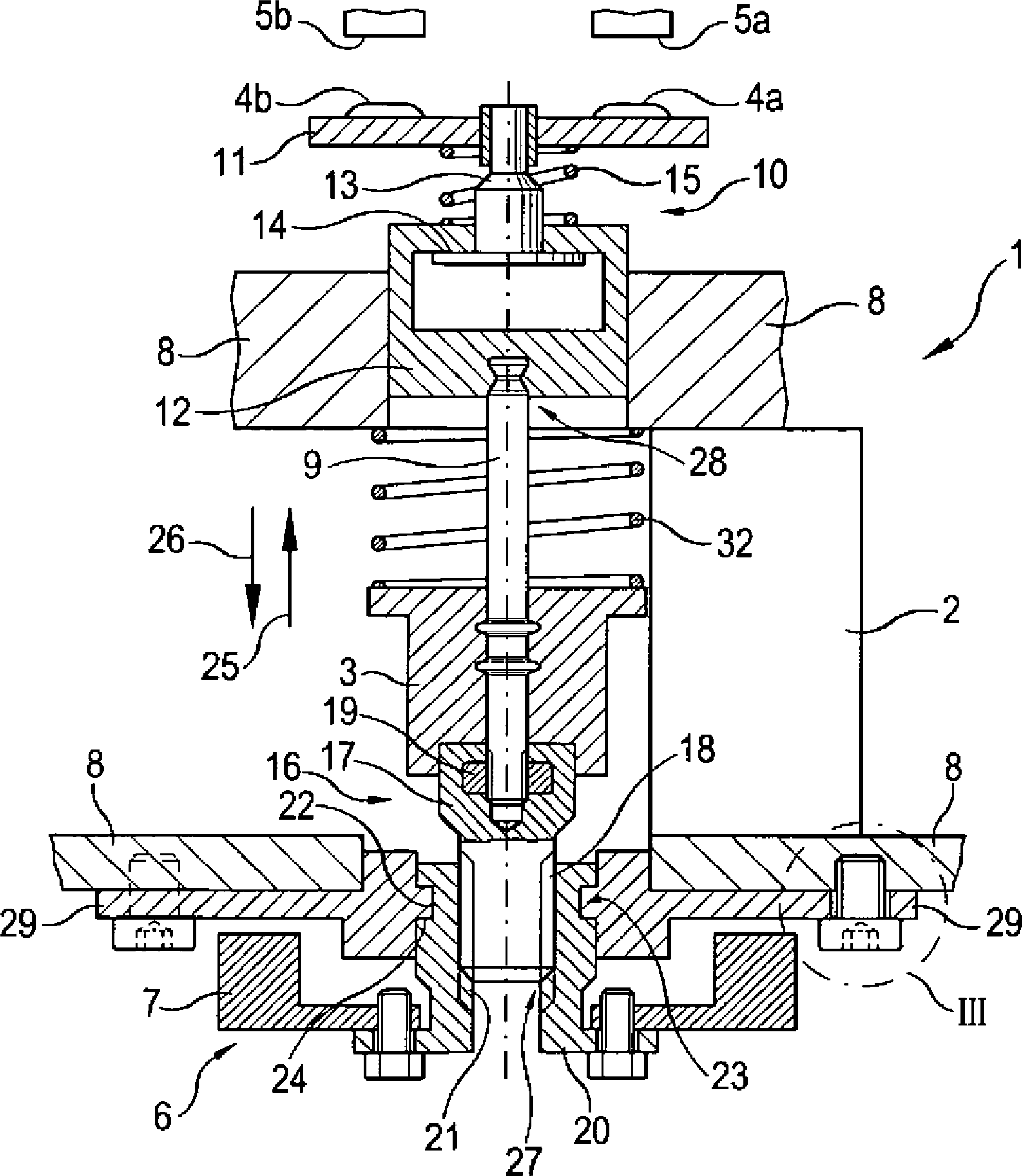
[0033] figure 1 and 2 Shown is an electrical contactor 1 according to the invention having a stator 2 and an armature 3 movable relative thereto, which is connected to at least one contact area 4a or 4b, preferably two contact areas 4a and 4b . These contact areas 4a and 4b can be connected to preferably fixed counter contact areas 5a and 5b respectively. Furthermore, a propulsion device 6 in the form of a flywheel 7 is connected to the armature 3 .

[0034]The stator 2 positioned laterally to the armature 3 is fixedly connected to the housing 8 of the electrical contactor 1 . Furthermore, the activation and supply of the stator 2 are not shown here, which can include...


PUM


Abstract

The invention relates to an electrical contactor 1, particularly for use in railways, having a stator 2 and an armature 3, said armature 3 being connected to a contact region 4a, 4b and being movable from a first to a second position during a switch-on and/or a switch-off process of the contactor, wherein the contact region 4a, 4b is connected in at least one of said positions to a counter-contact region 5a, 5b for closing an electrical circuit, wherein a pushing device 6 is connected to the armature, which pushing device can be rotated relative to the armature 3, wherein the pushing device 6 pushes the armature 3, during the movement from the first to the second position of the switch-on and/or switch-off process at least at times in a supporting manner. The invention also relates to a method for switching on and/or off an electrical contactor 1, comprising the following steps: moving an armature 3 by activating and/or deactivating a stator; accelerating a rotation of a pushing device 6, said pushing device 6 being connected to the armature 3; and transferring at least a portion of the kinetic movement energy of the pushing device 3 to the armature 3, in a phase of the switch-on and/or switch-off process, in which a contact region 4a, 4b connected to the armature 3 comes into contact with and out of contact with a counter contact region 5a, 5b to support the armature movement.

Description

technical field [0001] The invention relates to an electrical contactor (Schaltschuetz), especially for use in railways, with a stator and an armature, which is connected to the contact area and which is used during the contactor switching and / or switching off process can be moved from a first position to a second position, wherein the contact area is connected to a mating contact area (Gegenkontaktbereich) in at least one of these positions to close the circuit; and a device for switching on and / or breaking approach to electrical contactors. Background technique [0002] Electrical contactors are known, in particular from the field of railway construction, which place the highest demands on their construction with regard to their wear resistance. The contact areas of the high power contactors used therein are especially exposed to enormous stresses. Due to the high current to be connected, especially in the Currents in the kA range result in high loads. In this case, th...

Claims


Application Information

Patent Timeline
IPC IPC(8): H01H50/54H01H1/50H01H3/00H01H3/40H01H50/30
CPCH01H3/40H01H50/305H01H1/50H01H50/546H01H3/001H01H3/28
Inventor A.伊尼纳托夫R.克拉利克
Owner SCHALTBAU GMBH
Why Eureka
Try Eureka