Handheld Blower

A blower and hand-held technology, applied in the field of hand-held blower, can solve problems such as poor grip balance and large size of the whole machine

Active Publication Date: 2017-06-06
POSITEC POWER TOOLS (SUZHOU) CO LTD
View PDF16 Cites 0 Cited by
  • Summary
  • Abstract
  • Description
  • Claims
  • Application Information

AI Technical Summary

Problems solved by technology

[0005] Based on this, it is necessary to provide a hand-held blowing machine for the problems of large size and poor grip balance of the hand-held blowing machine

Method used


Image

  • Handheld Blower
  • Handheld Blower
  • Handheld Blower

Examples


Embodiment Construction

[0020] The present invention will be further described below in conjunction with the accompanying drawings and embodiments.

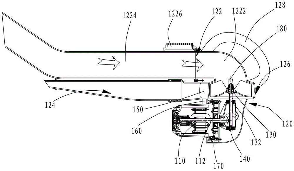
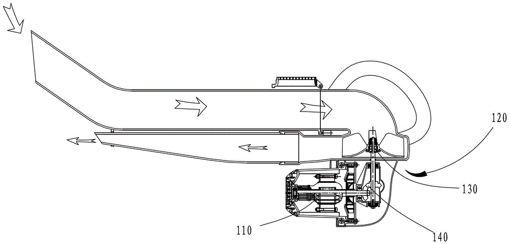
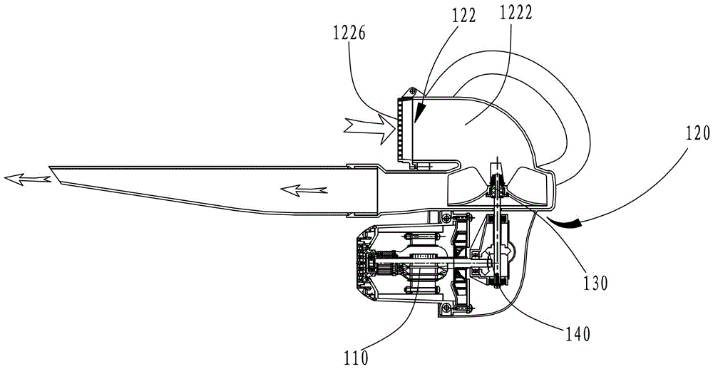
[0021] see figure 1 and figure 2 , a hand-held air blower 100, including a drive motor 110 and a housing 120, the drive motor 110 is fixed to the housing 120 to provide power for the hand-held air blower 100; the housing 120 is provided with Air outlet 122, air outlet 124, dust collecting outlet 126 and handle 128, described casing 120 is also provided with fan 130, the output shaft 132 of described fan 130 and the motor shaft 112 of drive motor 110 are connected by reduction gear 140, and The motor shaft 112 of the driving motor 110 and the output shaft 132 of the fan 130 form a predetermined shaft angle.

[0022] When the above-mentioned hand-held air blower is working, hold the handle 128, turn on the switch of the drive motor 110, the drive motor 110 rotates, and the drive motor 110 transmits power to the fan 130 through the reduction device 140,...


PUM


Abstract

A handheld blowing and sucking machine comprises a driving motor and a shell, wherein the driving motor is fixed on the shell; the shell is provided with an air inlet, an air outlet, a dust collecting opening and a handle; a fan is also arranged in the shell; an output shaft of the fan is connected with a motor shaft of the driving motor through a speed reducing device; and a preset axial angle is formed between the motor shaft of the driving motor and the output shaft of the fan. Under the condition that the output pressure of the fan is certain, the square of the revolving speed of the fan is inversely proportional to the square of the diameter of the square, the revolving speed of the fan is increased by reducing the diameter of the fan, so that the size of the fan is reduced, and the size of the shell is also reduced. Because the preset axial angle is formed between the driving motor and the fan, the size of the whole handheld blowing and sucking machine is reduced in the axial direction of the output shaft of the fan, the spatial arrangement of the whole handheld blowing and sucking machine is compact, the holding balance is improved, and the using convenience is improved.

Description

technical field [0001] The invention relates to a cleaning tool, in particular to a hand-held blower. Background technique [0002] Hand-held blower is widely used because of its convenient operation, time-saving and labor-saving. [0003] A traditional hand-held blower generally includes a housing, a driving motor and a fan. The housing is provided with an air inlet, an air outlet, and a handle. The driving motor directly drives the fan to rotate. In the working mode of suction, operate with the handle, the suction generated by the fan absorbs external debris through the suction port, enters the dust bag, and collects them centrally; in the working mode of blowing, operate with the handle, the fan The generated suction is discharged through the air outlet provided on the casing, and the dust on the surface of the object is blown to clean the surface of the object. [0004] However, the traditional drive motor generally drives the motor to directly drive the fan to rotate....

Claims


Application Information

Patent Timeline
Patent Type & Authority Patents(China)
IPC IPC(8): B08B5/02B08B5/04
CPCB08B5/02B08B5/04
Inventor 喻学锋周生魁
Owner POSITEC POWER TOOLS (SUZHOU) CO LTD
Why Eureka
Try Eureka