Rolling control device and rolling control method

A technology for control devices and rolling materials, applied in the direction of rolling mill control devices, metal rolling, metal rolling, etc.

Active Publication Date: 2014-07-02
HITACHI LTD
7 Cites 3 Cited by

AI-Extracted Technical Summary

Problems solved by technology

Therefore, only the plate thickness between the rolling stands and the rolling stands (hereinafter referred to as "intermediate plate thi...

Abstract

The invention provides a rolling control device and a rolling control method, wherein the plate thickness between the pedestals can be calculated in a high-efficiency manner without additionally arranging any special hardware. The centring arrangement of a plurality of rollers is adopted, the thickness of the plate on the outlet side opposite to the roller of the last segment of the rolling sequence can be acquired, and based on the plate thickness of the outlet side, the plate thickness of the inlet side can be calculated according to the mass-flow conservation principle. The calculated result of the plate thickness of the inlet side opposite to the roller can be used for the repeated calculation of the plate thickness of the rolled material sent by the roller pair abutting against the front part, and therefore the plate thickness of the inlet side of the roller pair can be calculated, the error between the plate thickness of the inlet side of the roller pair arranged on the starting end and the plate thickness of the roller pair calculated by using other methods can be calculated. Based on the calculated errors, the above mentioned errors can be corrected.

Application Domain

Roll mill control devicesMetal rolling arrangements

Technology Topic

EngineeringMechanical engineering

Image

  • Rolling control device and rolling control method
  • Rolling control device and rolling control method
  • Rolling control device and rolling control method

Examples

  • Experimental program(1)

Example Embodiment

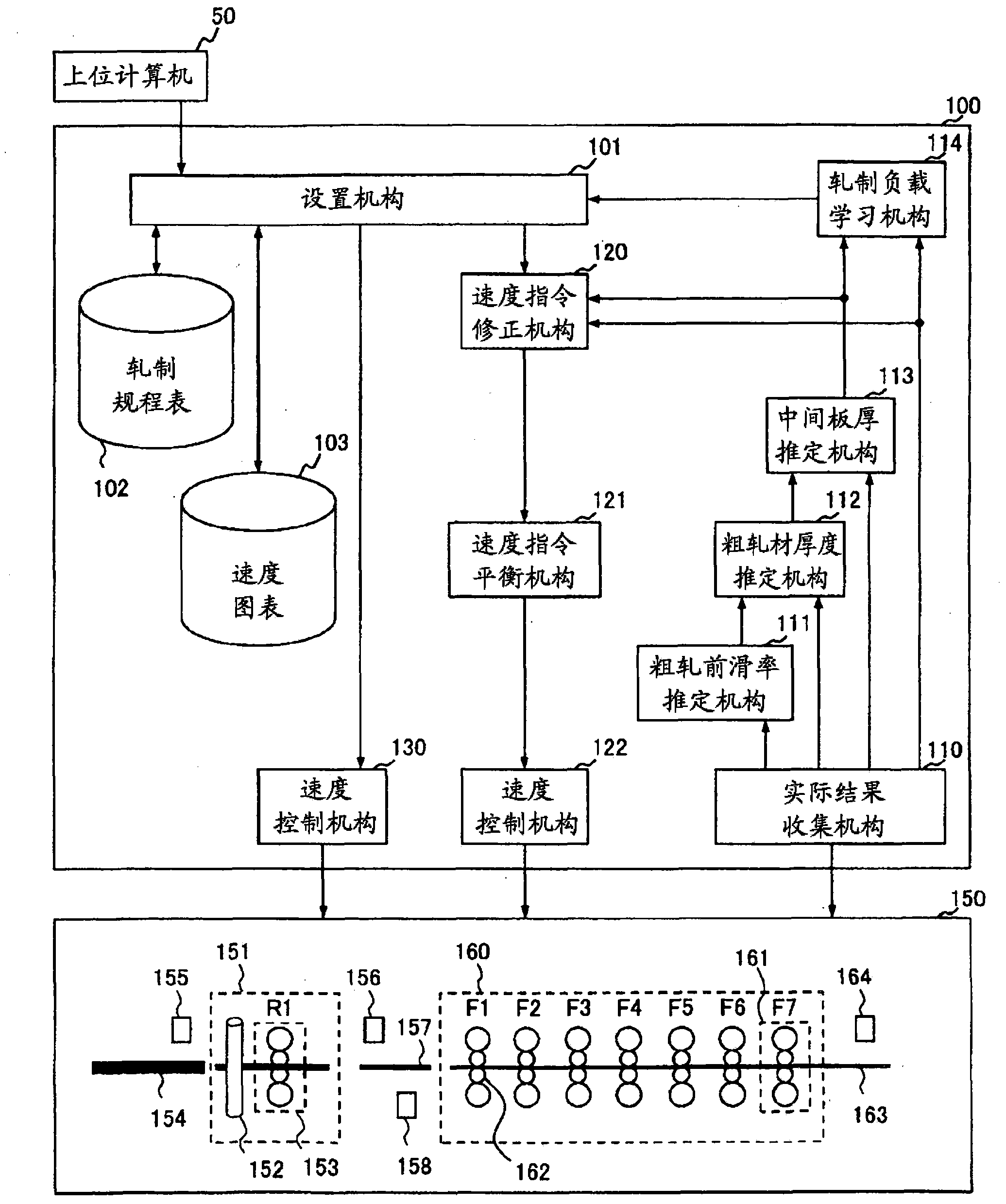
[0037] Hereinafter, embodiments of the present invention will be described in detail using the drawings. In the rolling system of the present embodiment, rough rolling in which a raw material slab is reciprocally rolled to an intermediate thickness, and finish rolling in which the rough-rolled steel material is continuously rolled to a target thickness with high precision are performed. Then, in finish rolling, based on the error between the plate thickness on the entry side of the initial mill stand obtained by the mass flow conservation law and the plate thickness on the entry side of the initial mill stand obtained by different methods, the The intermediate plate thickness obtained by the mass flow conservation law is corrected. This makes it possible to increase the accuracy of the estimated value of the intermediate thickness. As a result, it is possible to stabilize the rolling at the front end of the steel sheet and produce a high-quality steel sheet.
[0038] figure 1 It is a block diagram showing the functional configuration of the rolling control device according to the embodiment of the present invention. The control device 100 of the hot tandem rolling mill receives various signals from a control target 150 , that is, a rolling mill including a roughing stand and a finishing stand, and outputs control signals to the control target 150 . First, the configuration of the control object 150 will be described. In this embodiment, the control object 150 is a hot rolling mill including a rough rolling mill 151 and a finishing mill 160 , and the rough rolling mill 151 is composed of a vertical rolling mill 152 and a horizontal rolling mill 153 in the example of the drawing.
[0039] In addition, the finishing mill 160 is comprised by several rolling stands, and in this Example, it is comprised as the structure which arrange|positioned seven rolling stands 161 of F1 to F7 continuously. exist figure 1 In this process, the steel plate to be rolled moves from left to right, and the rough rolling mill 151 reciprocates the high temperature slab 154 extracted from the heating furnace which is a step before the rough rolling mill 151 . One rolling is called a pass, and rolling is usually performed in about 3 to 7 passes.
[0040] In the rough rolling mill 151 , the slab is reciprocated, the vertical rolling mill 152 is used to adjust the width of the slab, and the horizontal rolling mill 153 is used to reduce the thickness of the slab. In the rough rolling mill 151 , the slab 154 is finally processed into a rough rolled material 157 having a thickness of about 30 mm, and is transported to the finish rolling mill 160 . The rough-rolled material 157 is also called a thick bar, an input bar, a transfer bar, and the like.
[0041]In the finish rolling mill 160, the rough-rolled material 157 is sequentially processed and thinned by rolling by each rolling stand 161, and the steel plate having the final target thickness on the exit side of F7, for example, a steel plate of about 1 mm to 15 mm 163 are discharged. In the rough rolling mill 151 and the finishing mill 160, it is the horizontal rolling mill 153 and the work rolls 162 provided in each rolling mill stand 161 that directly roll the slab 154, the rough rolling material 157, and the steel plate 163. The speed refers to the peripheral speed of the work roll 162 .
[0042] As a detector for grasping the states of the slab 154, the rough-rolled material 157, and the steel plate 163, in this embodiment, a strip width gauge 155 for detecting the width of the slab is provided on the entry side of the rough rolling mill 151. In addition, a strip width gauge 156 for measuring the width of the rough rolling material 157 and an HMD (Hot Metal Detector) 158 for detecting the arrival of the rough rolling material 157 are provided on the exit side of the rough rolling mill 151 . In addition, a multifunctional crown gauge 164 for measuring the thickness and width of the steel plate 163 is provided on the exit side of the final stand ( F7 ) of the finish rolling mill 160 .
[0043] Although omitted in this embodiment, actually, as a detector for grasping the state of the slab 154, the rough-rolled material 157, and the steel plate 163, a thermometer or a shape measuring the flatness of the plate is provided at each position as necessary. Various detectors such as a cutting profile meter (Japanese: croup profile meter) for measuring the shape image of the front end of the rough-rolled material 157 , and a surface flaw meter for detecting surface defects of the steel plate 163 .
[0044] Next, the configuration of the control device 100 for the hot continuous rolling mill will be described. In the control device 100 of the hot rolling mill, the setting mechanism 101 receives from the host computer 50 information necessary for rolling such as the steel type, target plate thickness, and target plate width for each steel plate to be rolled. Then, the setting mechanism 101 refers to the rolling schedule table 102 and the speed chart 103 to calculate the rolling load, the pressing position of the work roll 162 (gap between rolls), and the roll speed of the work roll 162 for each rolling stand 161 .
[0045] In addition, the actual result collecting means 110 collects the actual rolling results from the controlled object 150 or the control command value actually output to the controlled object by the control device 100 of the hot rolling mill. The rough rolling forward slip rate estimating means 111 uses the data collected by the actual result collecting means 110 to estimate the forward slip rate during the rolling of the final stroke at the rough rolling mill 151 . The rough-rolled material thickness estimating unit 112 estimates the thickness of the rough-rolled material 157 based on the data collected by the actual result collecting unit 110 and the output of the rough-rolling slip rate estimating unit 111 . The intermediate plate thickness estimating unit 113 estimates the steel plate thickness between each rolling stand 161 of the finishing mill 160 (hereinafter referred to as the intermediate plate thickness) based on the data collected by the actual result collecting unit 110 , and then uses the rough-rolled material thickness estimating unit 112 to estimate The thickness of the rough-rolled material 157 corrects the estimated intermediate plate thickness, thereby estimating the final intermediate thickness.
[0046] Here, the front slip ratio refers to a value corresponding to the ratio of the peripheral speed of the work roll to the exit speed of the plate rolled by the work roll, as shown in the following formula (1), by entering the thickness H of the side, the exit side Plate thickness h, flat roll diameter R', deformation resistance K p , Entry tension t b and the exit tension t f come to ask for it.
[0047] f=F (H, h, R', K p , t b , t f )…(1)
[0048] Further, the rolling load learning means 114 calculates a learning coefficient used for calculating the rolling load using the data collected by the actual result collecting means 110 and the plate thickness estimated by the intermediate plate thickness estimating means 113 . The speed command correcting means 120 corrects the roll speed calculated by the setting means 101 for the steel plate to be rolled next time. The speed command balance mechanism 121 acquires the output of the speed command correction mechanism 120, and limits the speed correction amount relative to each of the rolling stands 161 within the upper and lower limits in consideration of the balance between the rolling stands.
[0049] The speed control means 122 performs speed control in response to the final roll speed command. The pressing position control mechanism 130 uses signals such as the difference between the actual result sheet thickness and the target sheet thickness (sheet thickness deviation) measured by the multi-function crown meter 164 to control the actual pressing position command output by the setting mechanism 101. Press the position.
[0050] Hereinafter, the operation of each part will be described in detail. exist figure 2 The detailed structure of the rough rolling mill 151 is shown in . In the rough rolling mill 151 , the slab 154 is sequentially processed and thinned by reciprocating rolling, and at the same time, the vertical rolling mill 152 is used to control the width so that the rough rolling material 157 has a predetermined width. In the rolling of the final pass of the rough rolling mill 151 , the rough rolling material 157 is sent out to the finish rolling mill 160 .
[0051] Peripheral velocity V of the work roll 201 included in the horizontal rolling mill 153 during the rolling of the final pass r In contrast, the velocity V of the rough-rolled material 157 rolled by the work roll 201 s The use front slip rate is represented by the following formula (2).
[0052] V s = (1+f)·V r …(2)
[0053] Here f is the forward slip rate, although it represents the speed V of the rough rolled material 157 s Relative to the peripheral speed V of the work roll 201 r As fast as (1+f) times, but cannot detect f directly. Therefore, f is estimated using the actual rolling results.
[0054] It should be noted that the final stroke under the rough rolling is the rolling process immediately before the material to be rolled is inserted into the finishing mill 160 for finish rolling, and is carried out from the beginning to the end of the material to be rolled relative to the rough rolling mill 151 Final roughing treatment in one pass.
[0055] exist image 3 The figure in the figure shows the process of estimating the forward slip rate by the rough rolling forward slip rate estimating means 111 . Let the time when the horizontal rolling mill 153 starts the rolling of the final stroke be t 1 , the time when the rolling of the final stroke ends is set as t 3 , set the peripheral speed of the work roll 201 as V r (t). In addition, let the time when the rough-rolled material 157 reaches the HMD 158 be t 2 , set the distance between the horizontal rolling mill 153 and the HMD158 as L hmd.
[0056] In the present embodiment, the arrival of HMD 158 is used as the reference point for distance calculation, and the rough rolling material 157 needs to reach the distance calculation reference point during rolling by the horizontal rolling mill 153 . t 2 3. Between the rough rolling mill 151 and the finish rolling mill 160, generally as a device capable of detecting the arrival of the rough rolling material 157, a strip width meter 156 that outputs a "slab presence detection signal" is provided, and a "slab arrival signal" is output to measure the rough rolling material 157. Cutting contour gauge of the front end shape of the machine, etc. Also consider using these signals as reference points for distance calculations without setting the HMD158 in place.
[0057] like image 3 As shown, the pre-rough rolling slip rate estimation mechanism 111 first obtains the loading signal of the horizontal rolling mill 153 (S301), and obtains t 1. Next, rough-rolling front slip rate estimating means 111 acquires a signal obtained by HMD 158 detecting the front end of rough-rolled material 157 (S302), and obtains t 2. Then, the slip ratio estimation mechanism 111 before rough rolling calculates the rotational circumference L of the work roll 201 by the following equation (3) by integrating the load from the horizontal rolling mill 153 to the circumferential speed of the work roll 201 at the tip detected by the HMD 158 wr1 (S303).
[0058] L wr 1 = ∫ t 1 t 2 v r ( t ) dt . . . ( 3 )
[0059] When calculating the rotation circumference L wr1 , the rough rolling forward slip rate estimating means 111 calculates the value of the average forward slip rate from the loading of the horizontal rolling mill 153 to the detection of the front end by the HMD 158 ( S304 ). Estimated value of forward slip rate f est It can be obtained by the following formula (4).
[0060] f est = L hmd /L wr...(4)
[0061] exist Figure 4 In the figure, the processing of the rough-rolled material thickness estimation means 112 is shown. like Figure 4 As shown, the rough-rolled material thickness estimation mechanism 112 acquires the thickness, length, and width of the slab 154 ( S401 ). Usually, these values ​​are values ​​previously measured in a previous process and sent from the host computer 50 , but in this embodiment, the slab width can be measured by the slab width meter 155 . In this way, the items included in the detector can be updated with the values ​​acquired by the control object 150, and the highest precision values ​​can be used.
[0062] Then, the rough-rolled material thickness estimating mechanism 112 acquires the value of the width of the slab 154 measured by the slab width meter 155 from the control object 150 (S402), and obtains the value of the horizontal rolling mill 153 in the final stroke of the rough-rolling mill 151. Circumferential length L of the work roll 201 from the start of rolling to the end of rolling wr2 (S403). As shown in the following formula (5), the circumference is the circumferential speed V r The value of (t) is at the start time t of rolling from the horizontal rolling mill 153 1 to the end of rolling t 3 obtained by integrating between them.
[0063] L wr 2 = ∫ t 1 t 2 v r ( t ) dt . . . ( 5 )
[0064] As shown in the following equation (6), if the rough-rolled material thickness estimation mechanism 112 uses the above equation (5) to obtain the circumference L of the work roll 201 wr2 , then through L wr2 Multiply the forward slip rate f est , obtain the length L of the rough rolled material 157 b.
[0065] L b = f est × L wr2...(6)
[0066] If the rough-rolled material thickness estimation mechanism 112 uses the above formula (6) to obtain the length L of the rough-rolled material 157 b , then for the slab 154 and the rough-rolled material 157 that is rolled by the roughing mill 151, focus on volume preservation, and use the slab thickness t s , slab width W s , slab length L s , the width of the rough rolled material W b And the length L of the rough rolled material b , use the following formula (7) to estimate the thickness t of the rough rolled material b. That is, the rough-rolled material thickness estimation mechanism 112 functions as a rough-rolled result acquisition unit.
[0067] t b =(t s ×W s × L s )/(W b × L b )...(7)
[0068] exist Figure 5 The middle circle shows the processing executed by the intermediate plate thickness estimation means 113 . The intermediate thickness estimating means 113 estimates the intermediate thickness based on the actual rolling results of the steel sheet 163 that has been rolled. like Figure 5As shown, the intermediate plate thickness estimation mechanism 113 obtains the value t of the plate thickness measured by the multi-functional crown meter 164 on the exit side of the final machine base (F7) 7 (S501).
[0069] On the inlet and outlet sides of F7, the product of plate thickness and plate velocity is conserved, that is to say, the law of mass flow conservation holds true. The intermediate plate thickness estimating means 113 estimates the F6 exit side plate thickness from the following equation (8) based on the law of mass flow conservation ( S502 ).
[0070] t 6 = t 7 ×V 7 ×(1+f 7 )/{V 6 ×(1+f 6 )}…(8)
[0071] Here, t 7 Indicates the measured F7 exit side plate thickness, v 7 Indicates the peripheral speed of the F7 work roll, f 7 Indicates the forward slip rate of F7, V 6 Indicates the peripheral speed of the F6 work roll, f 6 Indicates the forward slip rate of F6. That is, the intermediate plate thickness estimation means 113 acquires the value t of the plate thickness measured by the multi-function crown gauge 164 7 The exit-side plate thickness acquisition unit functions as a plate thickness calculation unit that calculates the exit-side plate thickness of each stand based on the law of mass flow conservation.
[0072] as the forward slip rate f 6 , f 7 , the value calculated by the setting mechanism 101 before the rolling of the steel plate is used. The calculation is performed using the above-mentioned formula (1), and since it is calculated using the estimation of the mathematical formula, it is a value including a certain error, and the intermediate plate thickness estimated from this is also superimposed with an error. Correction of this error is performed in S505 and S506 described later. This is one of the gist of this embodiment.
[0073] The middle plate thickness estimating mechanism 113 repeats the same processing as the above formula (8), thereby estimating the exit side plate thickness of each rolling stand, that is, the middle plate under continuous rolling in the order of F5, F4, F3, F2, and F1. Thick (S503). In this manner, the intermediate thickness estimating means 113 sequentially performs calculations from the downstream rolling stands to obtain the thickness on the entry side of the stands from each forward slip ratio and the sheet thickness on the exit side of the rolling stands. In addition, the intermediate thickness estimating means 113 estimates the thickness t of the rough-rolled material 157 using the following equation (9) by the same process. b_est.
[0074] t b_est =t 1 ×V 1 ×(1+f 1 )/V b …(9)
[0075] Here, t 1 Indicates the estimated thickness of the F1 outlet side, V 1 Indicates the peripheral speed of the F1 work roll, f 1 Indicates the forward slip rate of F1, V b Indicates the speed of the rough-rolled material 157 .
[0076] Then, the intermediate plate thickness estimating means 113 calculates the thickness t of the rough-rolled material 157 estimated by the rough-rolled material thickness estimating means 112. b and the estimated rough-rolled thickness t b_est The deviation between △t b (S505). In addition, the intermediate plate thickness estimation mechanism 113 uses the following formula (10), and uses Δt b The estimated value of the intermediate plate thickness is corrected, and the intermediate plate thickness used for calculation by the learning means 101 or the speed command correcting means 120 is calculated ( S506 ).
[0077] t i_est = t i +△t b ×(t i / t b_est )...(10)
[0078] Here, t i Indicates the exit-side plate thickness of the Fi frame estimated in S502 and S503. That is, the intermediate plate thickness estimation mechanism 113 functions as an error correction unit.
[0079] In this way, in this embodiment, based on the measurement results of the plate thickness gauge installed on the exit side of the rolling stand at the last stage of the continuous rolling mill, the calculation according to the law of mass flow conservation is performed to calculate the flow rate of each stand. The plate thickness on the entry side. The thickness on the entry side calculated in this way is the thickness on the exit side of the rolling stand arranged immediately before it, so the calculation based on the law of conservation of mass flow is repeated, and the exit side of the rolling stand of each stage can be sequentially obtained. Plate thickness, that is, the middle plate thickness.
[0080] Using such repeated calculations based on the law of conservation of mass flow, the thickness of the entry side of the rolling stand installed at the beginning of the tandem rolling mill and the figure 2 The error between the plate thickness of the rough-rolled material 157 obtained by the method described in , that is, the thickness of the entry side of the continuous rolling mill, is corrected for the error of each intermediate plate thickness obtained according to the mass flow conservation law. It is one of the gist of this embodiment to improve the estimation accuracy of the intermediate plate thickness by such processing.
[0081] In addition, in this embodiment, when correcting each intermediate plate thickness obtained by the law of conservation of mass flow rate, the plate thickness on the entry side of the tandem rolling mill obtained by the law of conservation of mass flow rate and that obtained by other methods are used to correct each intermediate plate thickness. The correction value for correcting each intermediate thickness is determined based on the error between the thicknesses on the entry side of the tandem rolling mill. At this time, as shown in the above formula (10), the correction value is calculated by multiplying the ratio of the plate thickness to be corrected to the plate thickness on the entry side of the tandem rolling mill obtained from the mass flow conservation law by the above error. That is, in the mathematical formula contained in the above formula (10), Δt b ×(t i / t b_est ) is a part indicating the correction value. By such processing, it is possible to ideally obtain the correction of each intermediate plate thickness.
[0082] It should be noted that, based on the error between the plate thickness on the entry side of the continuous rolling mill obtained by the law of mass flow conservation obtained as described above and the plate thickness on the entry side of the continuous rolling mill obtained by other methods, the calculated Regarding the correction value of each intermediate plate thickness, in addition to the method described above, there is also a method of distributing the above-mentioned error to each intermediate plate thickness. The distribution method can be determined based on the reduction ratio of each rolling stand in addition to the method of equal distribution.
[0083] By improving the estimation accuracy of the intermediate thickness through such processing, the accuracy of the processing after using the intermediate thickness can be improved. Next, subsequent processing will be described. exist Image 6 The middle indicates the processing of the rolling load learning unit 114 . The rolling load learning mechanism 114 estimates the rolling load of each stand based on the actual results of rolling temperature and rolling speed acquired from the control object 150, the estimated value of the plate thickness on the side of the stand entry and exit, etc. 150 Comparing the obtained rolling loads of the actual results of each stand, calculates a rolling load correction coefficient for correcting the rolling load estimated value. That is, the rolling load learning means 114 functions as a rolling load calculation unit.
[0084] like Image 6 As shown, the rolling load learning means 114 acquires the actual rolling load results of F1 to F7 during the rolling from the controlled object 150 ( S601 ). Next, the rolling load learning unit 114 performs rolling load estimation calculation for each stand using the rolling load prediction formula acquired from the controlled object 150 ( S602 ).
[0085] The rolling load is the load required to reduce the thickness of the entrance side to the thickness of the exit side. The greater the thickness of the entrance side and the smaller the thickness of the exit side, or the greater the deformation resistance, the greater the rolling load. value. In addition, the more accurate the values ​​of the entry-side thickness and the exit-side thickness are, the more accurately the rolling load can be estimated. The rolling load prediction formula is represented by the following formula (11) using, for example, the strip width w, the deformation resistance Kp, the reduction force function Qp, and the friction coefficient μ.
[0086] P=g(w, K p , Q p , t f , t b , R', H, h, μ)...(11)
[0087] In the above formula (11), t estimated from the formula (10) is used for the inlet-side thickness H and the outlet-side thickness h i_est. of course i_est It can also be used as the thickness of the entry side of the (i+1) machine frame. Use the actual result obtained from the control object 150 as the rear tension t b , front tension t f , flat roll diameter R' or deformation resistance K p , Depressive force function Q p The calculation of is also performed using the actual result value or a value calculated from the actual result value.
[0088] Then, the rolling load learning means 114 estimates the rolling load correction coefficient Z from the actual result load and the estimated load using the following equation (12): p.
[0089] (Z p ) i =(P act ) i /(P est ) i...(12)
[0090] Here, (P act ) i is the actual result load of the i-th stand of the finishing mill 160 acquired from the control object 150, (P est ) i is the estimated load of the i-th base calculated by formula (11), (Z p ) i is the rolling load correction factor for the i-th stand. (Z p ) i It is used in the estimation calculation of the rolling load of the steel plate 163 to be rolled next time in the setting mechanism 101 .
[0091] exist Figure 7 The middle indicates the processing performed by the installation mechanism 101 . The setting mechanism 101 receives information necessary for rolling such as steel type, target plate thickness, and target plate width from the host computer 50, and then calculates control commands such as the pressing position and roll speed of the rolled steel plate based on the information. Originally, the installation mechanism 101 performs this calculation for the rough rolling mill 151 and the finishing mill 160 , but in this embodiment, the calculation for the rough rolling mill 151 is omitted, and only the content of the installation calculation for the finishing mill 160 as the scope of application of the present invention is described.
[0092] In the finish rolling mill 160 , the tip of the steel plate 163 is rolled according to the control command output from the setting mechanism 101 . Therefore, in order to obtain a desired thickness of the steel plate from the tip, it is necessary to make the rolling load and the pressing position of the work roll 162 appropriate. In addition, in order to stabilize the operation when the steel plate bites into the downstream stand, it is necessary to set the roll speed of each stand to a well-balanced command that does not affect the mass flow rate of the steel plate 163 .
[0093] like Figure 7 As shown, the setting mechanism 101 obtains the information corresponding to the extent to which the rough-rolled material 157 and the steel plate 163 are thinned, that is, rolling Procedure (S701). exist Figure 8 A configuration example of the rolling schedule table 102 is shown in . Figure 8 The rolling schedule involved in the example is stored in the form of the percentage of the value rolled by each rolling stand 161 relative to the thickness difference with respect to the thickness difference between the rough-rolled material 157 and the steel plate 163, and each rolling schedule is based on the rolling The steel type, plate thickness and plate width of the steel plate are layered.
[0094]For example, consider a rough-rolled material 157 of 35 mm in which the steel type is SS400, the target plate thickness is 2.5 mm, and the target plate width is 900 mm. Comply with the level where the target plate thickness is 2.0-3.0mm and the target plate width is 1000mm or less. Since the rough rolling material 157 of 35 mm is rolled into the steel plate 163 of 2.5 mm, 24% of it is rolled in F1 and 16% of it is rolled in F2 with respect to a plate thickness difference of 32.5 mm. That is, rolling represented by the following formula (13) is performed at F1 to roll a 35 mm rough-rolled material to 35 mm-7.8 mm, that is, 27.2 mm.
[0095] 32.5mm×24/100=7.8mm...(13)
[0096] Similarly, since it is 16% in F2, rolling represented by the following formula (14) is performed, and the 27.2mm plate is rolled to 27.2mm-5.2mm, ie, 22.0mm.
[0097] 32.5mm×16/100=5.2mm...(14)
[0098] For a certain level, the sum of the numerical values ​​of each rolling stand in the rolling schedule is 100, and when the same calculation procedure is repeated, the outlet thickness of F7 as the final stand becomes 2.5 mm as the target thickness. In this way, in S701, the setting mechanism 101 retrieves the corresponding hierarchical position of the rolling schedule table 102 according to the steel type, plate thickness, and plate width of the steel plate to be rolled next time received from the host computer 50, and obtains the rolling position of each rolling stand. quantity.
[0099] It should be noted, Figure 8 The rolling schedule shown can also be based on the above Δt b It is used to determine the correction amount when correcting the thickness of each intermediate plate. That is, based on the error between the plate thickness on the entry side of the continuous rolling mill obtained by the mass flow conservation law obtained as described above and the plate thickness on the entry side of the continuous rolling mill obtained by other methods, the It is also possible to use the correction value of the intermediate plate thickness Figure 8 Values ​​for each mill stand for the rolling schedule shown.
[0100] For example, when correcting the plate thickness on the entry side of F1, apply Δt b 100% of , when correcting the sheet thickness on the exit side of F1, that is, the entry side of F2, 76% obtained by subtracting 24 from 100 is applied. In addition, when correcting the plate thickness of the exit side of F2, that is, the entry side of F3, 80% obtained by subtracting 16 from 76 is applied. In this way, by distributing the error according to the distribution of the reduction amount to each rolling stand, it is also possible to ideally correct the error of each intermediate plate thickness.
[0101] Next, the setting mechanism 101 acquires the speed map from the speed map 103 ( S702 ), and calculates the roll speed of each rolling stand. exist Figure 9 The structure of the speed map 103 is shown in . With respect to the steel type, target plate thickness, and target plate width of the steel plate 163, the speed when the front end of the steel plate 163 is discharged from F7, which is the final rolling stand, that is, the initial speed, the first acceleration after that, the second acceleration, and the second speed are stored in each hierarchy. Acceleration, maximum speed, deceleration at the time of decelerating from the maximum speed to the final speed at the end of the rolled steel plate 160, and the final speed.
[0102] The installation mechanism 101 judges the steel type, plate thickness, and plate width of the steel plate 163 and extracts a corresponding velocity map from the velocity map 103 . For example, when the steel type is SUS304, the plate thickness is 2.0 to 3.0 mm, and the plate width is 100 mm or less, the initial speed is set to 650 mpm, the first acceleration is set to 2 mpm/s, and the second acceleration is set to 12 mpm /s, the stable speed is set to 1050mpm, the deceleration is set to 6mpm/s, and the final speed is set to 900mpm.
[0103] Next, the setting mechanism 101 estimates the rolling temperature ( S703 ). The temperature of the rough-rolled material 157 and the steel plate 163 is estimated by combining the value detected by the thermometer and the temperature prediction calculation which took heat radiation, heat transfer, etc. into consideration. The method for estimating the temperature is often introduced in literature on thermodynamics, etc., and thus detailed description thereof will be omitted.
[0104] Then, the installation mechanism 101 calculates a value corresponding to the hardness of the steel plate rolled by each rolling stand, that is, deformation resistance ( S704 ). The deformation resistance is described in various documents, and it is obtained by the following equation (15) using the estimated steel plate temperature T during rolling as a representative calculation formula.
[0105] kf=Kε n (dε/dt) m exp(A/T)...(15)
[0106] Here, ε is the deformation, (dε/dt) is the deformation speed, and K, n, m, A are constants determined by each steel type.
[0107] Next, the setting mechanism 101 calculates the roll speed of each rolling stand ( S705 ). The speed map acquired at S702 is the exit-side strip speed of F7, based on this map, the exit-side strip speed of each rolling stand is calculated as follows. First, the exit-side plate speed of each rolling stand is calculated by the following formula (16).
[0108] vs. i =Vs 7 × h i /h 7...(16)
[0109] Here, Vs i Indicates the exit speed of the i-th machine base, h i Indicates the exit side plate thickness of the i-th frame, h 7 Indicates the exit thickness of the 7th stand (final rolling stand).
[0110] Next, the setting mechanism 101 calculates the roll speed of each rolling stand from the exit plate speed of each rolling stand using the forward slip ratio. When the front slip ratio is used, there is a relationship of the following formula (17) between the roller speed and the exit plate speed.
[0111] VR i =Vs i / f i...(17)
[0112] Here, Vr i Indicates the roller speed of the i-th stand, f i Indicates the forward slip rate of the i-th base.
[0113] Then, the installation mechanism 101 calculates the forward slip rate for each rolling stand, and obtains the roll speed of each rolling stand. In addition, the installation mechanism 101 calculates the rolling load ( S706 ). The rolling load is calculated by the above formula (11). Finally, the setting mechanism 101 calculates the pressing position (distance between rolls) of the work rolls 162 ( S707 ). The basic part of the calculation of the pressing position is represented by the relational expression of the following formula (18), but actually various correction terms are added in order to improve the calculation accuracy.
[0114] S=h-P/k...(18)
[0115] Here, S represents a pressing position, P represents a rolling load, and K represents a rolling mill spring constant.
[0116] The setting mechanism 101 outputs the roll speed and the rolling position calculated as described above as control commands corresponding to the steel plate to be rolled next time. Such processing is performed based on the high-accuracy intermediate plate thickness as described above, so that the actual rolling phenomenon, especially the rolling result up to the leading end of the steel plate where the feedback control is stabilized, can be brought close to a desired target value.
[0117] exist Figure 10 The structure of the speed command correction mechanism 120 is shown in detail in . The speed command correction mechanism 120 is made up of the following structures: the front end value extraction mechanism 1001, which extracts the rolling data of the front end portion of the steel plate 163 rolled last time according to the data collected by the actual result collection mechanism 110 from the control object 150; the front end value storage The mechanism 1003 stores the value extracted by the front-end value extracting mechanism 1001; the stable value extracting mechanism 1002 extracts the roll speed, rolling load, pressure Lower position; stable value storage mechanism 1003, which stores the value extracted by the stable value extraction mechanism 1002; speed correction value calculation mechanism 1010, which obtains the contents of the front-end value storage mechanism 1003 and the stable value storage mechanism 1004, relative to the next rolling The steel plate corrects the roll speed calculated by the setting mechanism 101 .
[0118] exist Figure 11 The middle indicates the processing of the front-end value extracting means 1001 . The front end value extracting means 105 acquires the values ​​of the pressing position, rolling load, and roll speed when the front end of the steel plate 163 is rolled, for each rolling stand, from the output of the actual result collecting means 110 . In this embodiment, the actual result value is obtained for the pressing position and the rolling load, and the set value output by the speed control mechanism 122 is obtained for the roll speed.
[0119] like Figure 11 As shown, the front end value extracting mechanism 1001 judges whether or not the discharge length (rolling length) of the steel plate 163 in each rolling stand has reached a certain length ( S1101 ). The rolling length is usually included in the signal acquired from the control object 150, and the speed of the steel plate 163 estimated from the roll speed of each rolling stand using the forward slip ratio is integrated and calculated using the relationship of the above formula (17). In this embodiment, the data of the front end portion are extracted focusing on the rolling length.
[0120] When it is determined in S1101 that the discharge length of the steel plate 163 has not reached the predetermined length (S1101/NO), the front end value extracting mechanism 1001 repeats the process of S1101. When it is determined that the discharge length has reached a certain length (S1101/YES), the front-end value extracting means 1001 acquires the roll speed, pressing position, and rolling load of the rolling stand from the actual result collecting means (S1102).
[0121] Then, the front-end value extracting means 1001 judges whether the processing is completed for all the rolling stands (S1103), and if not (S1103/NO), the processing from S1101 is repeated for the rolling stands that have not been processed. The processing of the steel plate 163 by the front end value extracting mechanism 1001 ends when the acquisition of the roll speed, the rolling position, and the rolling load at the front end of the steel plate is completed for all the rolling stands (S1103/YES).
[0122] exist Figure 12 The middle indicates the processing of the stable value extracting unit 106 . The stable value extracting mechanism 106 acquires the values ​​of the rolling position, rolling load, and roll speed of each rolling stand at the same time when the rolling reaches the steady state from the output of the actual result collecting mechanism 104 . like Figure 12 As shown, the stable value extracting mechanism 106 judges whether or not the F7 discharge length (rolling length) of the steel plate 160 has reached a certain length (S1201). The rolling length is usually included in the signal obtained from the control object 150, and the relationship of the above formula (17) is used as the time when the speed of the steel plate 163 estimated from the roll speed of F7 using the forward slip rate is loaded at F7 Calculated as the result of integrating for the starting point.
[0123] When the rolling length of F7 is small, the rolling is in a transitional state immediately after biting into the steel plate 163, and when the rolling length is increased, the rolling becomes stable. Focusing on this point, in this embodiment, the rolling stability is judged focusing on the rolling length, and stability data are extracted. When it is determined that the F7 discharge length of the steel plate 163 has not reached the predetermined length (S1201/NO), the stable value extracting mechanism 106 repeats the process from S1201. When it is determined that the discharge length of F7 has reached a certain length (S1201/YES), the stable value extracting unit 106 acquires the roll speed, the pressing position, and the rolling load of each rolling stand from the actual result collecting unit (S1202).
[0124] exist Figure 13In the figure, the structure of the front-end value storage means 1003 and the stable value storage means 1004 is shown. The front end value storage unit 1003 stores the values ​​of the reduction position, rolling load, and roll speed which are extracted and output by the front end value extracting unit 1001 corresponding to the time when each rolling stand rolls the front end of the steel plate. For example, the reduction position in which F1 is stored is 30.40 mm, the rolling load is 2364 tons, and the roll speed is 27 mpm.
[0125] The stable value storage unit 1004 stores the values ​​of each rolling stand depression position, rolling load, and roll speed corresponding to when the rolling reaches a stable state and output by the stable value extracting unit 1002 . For example, the pressing position in which F1 is stored is 29.78 mm, the rolling load is 2380 tons, and the roll speed is 26.4 mpm.
[0126] exist Figure 14 The middle indicates the processing performed by the speed correction value calculation unit 1010 . like Figure 14 As shown, the speed correction value calculation unit 1010 first acquires the pressing position, rolling load, and roll speed of the front coil front end corresponding to each rolling stand from the front end value storage unit 1003 ( S1401 ). Next, the speed correction value calculating means 1010 acquires the pressing position, rolling load, and roll speed of the front coil stabilizing part corresponding to each rolling stand from the stabilizing value storing means 1004 ( S1402 ).
[0127] Next, the speed correction value calculation unit 1010 calculates the correction amount of the speed command for each rolling stand (S1403), using Figure 15 The calculation method is described in detail. exist Figure 15 In (a) and (b), the j-th stand (Fj) is taken as an example to show the movement of the front end of the steel plate and the rolling mill stand in a steady state. Figure 15 (a) is the action of the front end of the steel plate, and the rolling load, pressing position, and roll speed immediately after the front end 1503 of the rolled steel plate are respectively expressed as P act-top , S act-top , V set , the thickness of the plate on the out side of the Fj base is expressed as h.
[0128] on the other hand, Figure 15 (b) is the action after the rolling reaches a stable state. The front end 1503 of the steel plate is located on the exit side of F7 (the final rolling mill stand), and all the rolling mill stands are rolled to maintain balance. At this time, the rolling load, pressing position, and roll speed are respectively expressed as P act-stab , S act-stab , V stab , and the plate thickness at the outlet side of the Fj base is expressed as h. At this time, the product of the plate thickness and the plate speed (mass flow rate) is conserved. Therefore, the following equation (19) is obtained when the roll speed that should be at the tip is derived from the balanced state.
[0129] V top_est ·(1+f top ) · (S top +P top /M) = V stab ·(1+f stab ) · (S stab +P stab /M)...(19)
[0130] Here, V top_est Indicates the roll speed that should be used when rolling the front end of the steel plate, f top Indicates the forward slip ratio when rolling the front end of the steel plate, S top Indicates the pressing position when rolling the front end of the steel plate, P top Indicates the rolling load when rolling the front end of the steel plate, M indicates the rolling mill constant, V stab Indicates the roll speed when rolling the stable part of the steel plate, f stab Indicates the forward slip rate when rolling the stable part of the steel plate, S stab Indicates the pressing position when rolling the stable part of the steel plate, P stab Indicates the rolling load when rolling the stable part of the steel plate.
[0131] In the above formula (19), V·(1+f) corresponds to the plate speed, and (S+P/M) corresponds to the plate thickness. Here, if set to Then the following formula (20) is established.
[0132] V top_est ·(S top +P top /M) = V stab ·(S stab +P stab / M) ... (20)
[0133] Therefore, the following formula (21) holds.
[0134] V top_est =V stab ·(S stab +P stab /M)/(S stab +P stab /M+S top -S stab +(P top -P stab )/M)=V stab h/(h+S top -S stab +(P top -P stab )/M)...(21)
[0135] (S stab -P stab /M=h)
[0136] Similarly, the following equation (22) holds for F7 (final rolling stand).
[0137] V 7top_est =V 7stab h 7 /(h 7 +S 7top -S 7stab +(P 7top -P 7stab )/M)...(22)
[0138] In addition, since the final rolling stand is the starting point of speed control, and the roll speed does not change during rolling, the following equation (23) holds.
[0139] V 7stab =V 7set …(twenty three)
[0140] It is also possible to set the starting point of speed control on another machine base. The speed correction coefficient αi of each rolling stand is the ratio of the speed command set for the steel plate 163 rolled last time to the required speed command calculated from the roll speed in the balanced state of rolling. The appropriate speed command is to use the thickness of the steel plate at this time and the thickness of the steel plate when the front end of the steel plate is rolled, and convert the speed of the roll in the balanced state of rolling into the roll at the front end of the steel plate according to the law of mass flow conservation. obtained for speed.
[0141] That is, it can be calculated by the following formula (24).
[0142] αi=(V i·top_est /V i·set ) · (V 7·set /V 7·top_est ) = (V i·act_stab /V i·set )·h i /{(h i +S i·act_top -S i·act_stab +P i·act_top -P i·act_stab )/M i}·{(h 7 +S 7·act_top -S 7·act_stab +P 7·act_top -P 7·act_stab )/M 7}/h 7 …(twenty four)
[0143] Here, V i·act_stab Indicates the roll speed when the i-th stand rolls the stable part of the steel plate, V i·set Indicates the roll speed setting value when the i-th stand rolls the front end of the steel plate, hi represents the exit-side thickness of the i-th stand, S i·act_top Indicates the pressing position when the i-th stand rolls the front end of the steel plate, S i·act_stab Indicates the pressing position when the i-th stand rolls the stable part of the steel plate, P i·act_top Indicates the rolling load when the i-th stand rolls the front end of the steel plate, P i·act_stab Indicates the rolling load when the i-th stand rolls the stable part of the steel plate, M i Indicates the rolling mill constant of the i-th stand, V 7·act_stab Indicates the roll speed when the 7th stand rolls the stable part of the steel plate, V 7·set Indicates the roll speed setting value when rolling the front end of the steel plate in the 7th stand, h 7 Indicates the exit side plate thickness of the 7th frame, S 7·act_top Indicates the pressing position when rolling the front end of the steel plate in the 7th stand, S 7·act_stab Indicates the pressing position when the 7th stand rolls the stable part of the steel plate, P 7·act_top Indicates the rolling load when the 7th stand rolls the front end of the steel plate, P 7·act_stab Indicates the rolling load when the 7th stand rolls the stable part of the steel plate, M 7 Indicates the rolling mill constant of the 7th stand.
[0144] That is, from the roll speed, rolling load, and reduction position when rolling the front end of the steel plate rolled last time, and the roll speed, rolling load, and reduction position after the rolling of the steel plate reached a steady state, it is possible to calculate A correction value for correcting the roller speed calculated by the setting mechanism is obtained. Alternatively, in order to simplify the calculation, it is also conceivable to perform calculation as in the following equation (25).
[0145] αi=(V i·top_est /V i·set ) · (V 7·set /V 7·top_est ) = (V i·act_stab /V i· set )·h i /{(h i +S i·act_top -S i·act_stab +P i·act_top -P i·act_stab )/M i}...(25)
[0146] The speed correction value calculation means 1010 calculates the correction amount of the speed command for each rolling stand by such calculation. In addition, the speed command correction amount α7 of F7 (the last rolling stand) is 0 because it is the rolling stand that becomes the starting point of the speed command. The speed correction value calculation means 1010 judges whether or not the calculation of the speed correction amount has been completed for all the rolling stands (S1404), and if not completed (S1404/NO), the processing from S1401 is repeated. When the calculation of the speed correction amount is completed for all the rolling stands (S1404/YES), the processing is terminated.
[0147] exist Figure 16 The middle indicates the processing performed by the speed command balancing mechanism 121 . The speed command balance mechanism 121 acquires the speed command correction amount of each rolling stand output by the speed command correction mechanism 120, and when there is a rolling stand for which the correction amount exceeding the upper and lower limits is calculated, limits it within the limit, and A process of balancing the correction amounts of other rolling stands is performed. like Figure 16 As shown, the speed command balance mechanism 121 judges whether there is a rolling mill stand whose speed command correction exceeds the upper and lower limits ( S1601 ).
[0148] When there is no rolling stand exceeding the upper and lower limits (S1601/NO), the speed command balance mechanism 121 ends the process. When there is a rolling stand exceeding the upper and lower limits (S1601/YES), the speed command balancing mechanism 121 performs processing of limiting the speed command correction amount of the rolling stand to the upper and lower limits after S1602. First, the speed command balance mechanism 121 determines the rolling stand with the largest absolute value of the speed command correction amount, as shown in the following equation (26), the upper and lower limit values ​​of the speed command correction amount αL Divide by the maximum value of the absolute value of the speed command correction amount to calculate the speed correction balance amount α 0 (S1602).
[0149] alpha 0 = α L /|α max |...(26)
[0150] Here, α 0 Indicates the speed correction balance, α L Indicates the upper and lower limits of the speed correction amount, α max Indicates the maximum value of the absolute value of the speed correction amount.
[0151] Next, the speed command balance mechanism 121 utilizes the following equation (27), by making α 0 The correction amount after balancing is calculated by multiplying the correction amount of each rolling stand ( S1603 ).
[0152] alpha i-b = α 0 ·α i...(27)
[0153] Here, α i-b Indicates the speed correction amount after balance.
[0154] exist Figure 17 , schematically shows the processing content of the speed command balancing mechanism 121. Relative to the speed correction amount in the figure, α L Set the upper limit 1703 and the lower limit 1704 of the width. With the correction amount 1701 before balancing, the speed command correction amount of the first base (F1) becomes the largest, and deviates from the value of the upper limit 1703 together with the speed command correction amount of the second base (F2). Here, as the upper and lower limits of α L divided by α max , so as to obtain the speed correction balance α 0. In addition, the speed correction amount (white circle in the figure) before each balance is divided by the speed correction balance amount α 0 To obtain the balanced correction amount 1702 (the black circle in the figure).
[0155] The reduction position control mechanism 130 corrects the reduction position obtained from the setting mechanism 101 so as to reflect the change in the actual result of the rolling load and the difference between the actual result value plate thickness detected by the multi-function crown gauge 164 and the target plate thickness. command to output the corrected value to the control object 150 . The control of the pressing position is called AGC (Automatic Gauge Control 1), and various methods such as Bisra AGC, Monitor AGC, and Gauge meter AGC are known. In addition, if the pressing position changes, the value of the mass flow rate of the entry-side steel plate and the exit-side steel plate changes. In order to compensate for this, the stand where the press position is changed and the upstream stand seen from the stand are The roll speed changes.
[0156] The speed control means 122 controls the speed of the work rolls 162 using the speed command output from the speed command balancing means 110 and the value of the speed correction amount output from the position control means 130 under pressure as a command value. A speed control system is usually constituted by a proportional-integral control system called ASR (Automatic Speed ​​Control).
[0157] In this embodiment, the upper limit and lower limit of the speed command correction amount are set to be the same as absolute values, and even if they are different values, it is possible to max defined as α i The ratio to the upper and lower limit values ​​is handled in the same way. In addition, a configuration in which the speed balance mechanism 121 is omitted and the speed control mechanism 122 is operated in accordance with the speed command output from the speed command correction mechanism 109 may also be considered.
[0158] In addition, in the present embodiment, the extraction of the stable part data is carried out focusing on the rolling length, but it is also possible to directly use the values ​​of the rolling position, the rolling load, and the roll speed, and it is possible to determine the rolling effect by not changing above a certain value. Stability, and set it as a condition for stable data extraction.
[0159] In addition, in figure 2 The middle setting mechanism 101 calculates from the rolling schedule to calculate the rolling load, rolling position, and roll speed, but a method of calculating from the load balance is also known, and the present invention is also applicable in this case.
[0160] In addition, in the present invention, the peripheral speed of the work roll 162 is set as the correction object of the speed command, but even if the rotation speed of the main machine motor driving the work roll, the speed command of the main machine driver, etc. processing to achieve.
[0161] In addition, in figure 1 The control device 100 described in is realized by a combination of software and hardware. Here, for the hardware for realizing each function of the control device 100 of this embodiment, refer to Figure 18 Be explained. Figure 18 It is a block diagram showing a hardware configuration of an information processing device constituting the control device 100 of the present embodiment. like Figure 18 As shown, the control device 100 of this embodiment has the same configuration as an information processing terminal such as a general server and a PC (Personal Computer).
[0162] That is, the control device 100 of the present embodiment connects CPU (Central Processing Unit) 10 , RAM (Random Access Memory) 20 , ROM (Read Only Memory) 30 , HDD (Hard Disk Drive) 40 , and I/F 50 via channel 80 . made. In addition, an LCD (Liquid Crystal Display) 60 and an operation unit 70 are connected to the I/F 50 .
[0163] The CPU 10 is an arithmetic unit, and controls the overall operation of the control device 100 . The RAM 20 is a volatile storage medium capable of high-speed reading and writing of information, and the CPU 10 is used as a work area when processing information. The ROM 30 is a read-only nonvolatile storage medium, and stores programs such as firmware.
[0164] The HDD 40 is a nonvolatile storage medium capable of reading and writing information, and stores an OS (Operating System), various control programs, application programs, and the like. I/F50 connects and controls the channel 80 and various hardware, network and so on. In addition, the I/F 50 can also be used as an interface for exchanging information between various devices or inputting information to a rolling mill.
[0165] LCD 60 is a visual user interface for an operator to check the state of control device 100 . The operation unit 70 is a user interface such as a keyboard or a mouse for an operator to input information to the control device 100 . In such a hardware configuration, programs stored in ROM30, HDD40, or a recording medium such as an unillustrated optical disk are read by RAM20, and CPU10 performs calculations based on the programs to constitute a software control unit. The functions of the control device 100 according to the present embodiment are realized by a combination of the software control unit configured in this way and hardware.
[0166] It should be noted that, in the above-mentioned embodiment, the case where all functions are included in one information processing device has been described as an example. All the functions may be realized by one information processing device as above, or each function may be realized by distributing each function to more information processing devices.

PUM

no PUM

Description & Claims & Application Information

We can also present the details of the Description, Claims and Application information to help users get a comprehensive understanding of the technical details of the patent, such as background art, summary of invention, brief description of drawings, description of embodiments, and other original content. On the other hand, users can also determine the specific scope of protection of the technology through the list of claims; as well as understand the changes in the life cycle of the technology with the presentation of the patent timeline. Login to view more.
Why Eureka
Try Eureka