Fuel injection control device for internal combustion engine

a technology of control device and internal combustion engine, which is applied in the direction of electric control, fuel injection apparatus, charge feed system, etc., can solve the problems of exhaust emission and drivability that may be made worse, and achieve the effect of preventing exhaust emission and drivability

Active Publication Date: 2014-10-23
DENSO CORP
View PDF4 Cites 35 Cited by
  • Summary
  • Abstract
  • Description
  • Claims
  • Application Information

AI Technical Summary

Benefits of technology

[0021]The fuel injection control device for an internal combustion engine may include a part for prohibiting a partial lift injection other than the partial lift injection for correcting the injection pulse until the correction of the injection pulse of the partial lift inje

Problems solved by technology

When the variations in the injection quantity are increased, there is

Method used


Image

  • Fuel injection control device for internal combustion engine
  • Fuel injection control device for internal combustion engine
  • Fuel injection control device for internal combustion engine

Examples


Embodiment Construction

[0038]Hereinafter, an embodiment of embodying a mode for carrying out the present disclosure will be described.

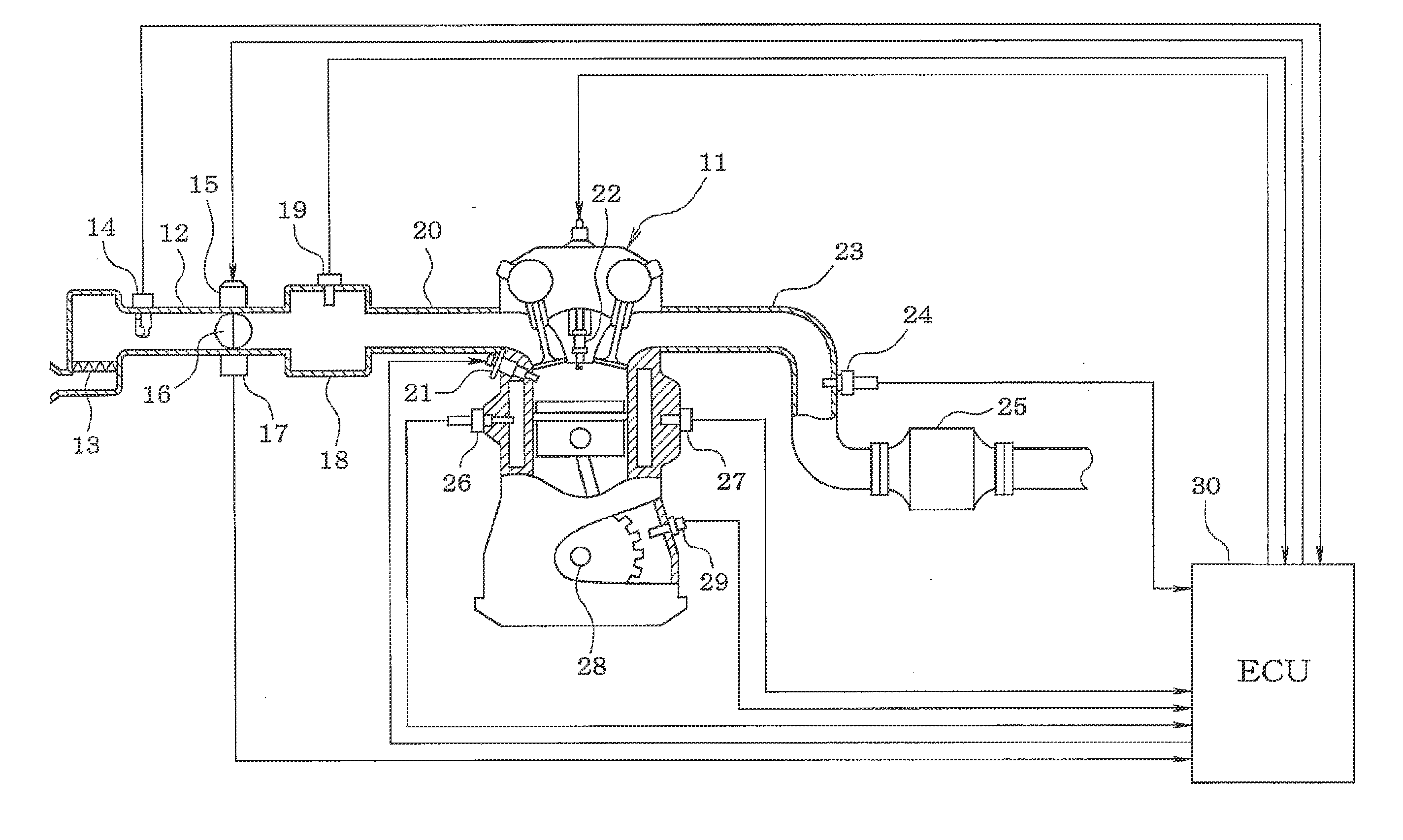
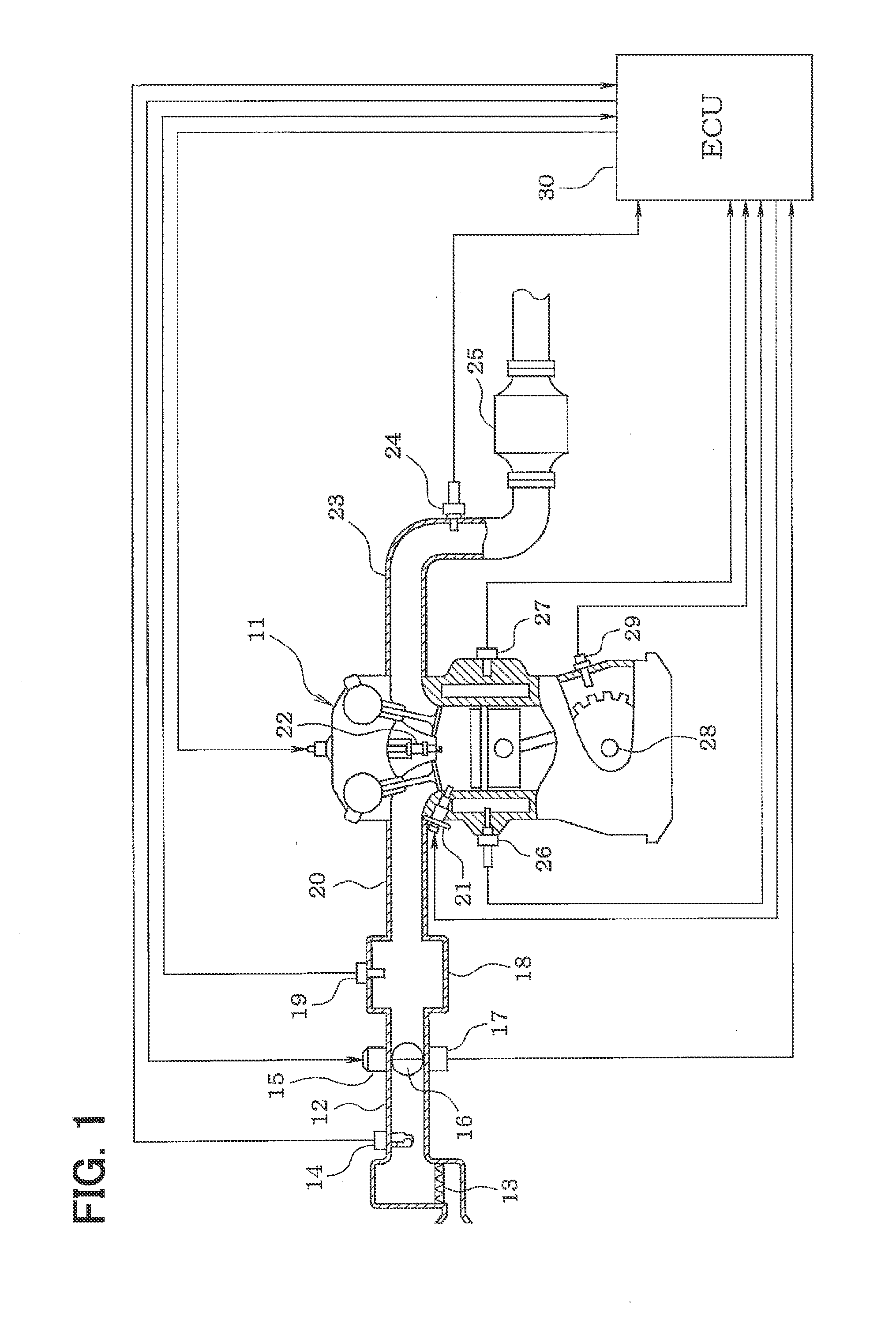
[0039]A direct injection type engine 11 of an internal combustion engine of a direct injection type has an air cleaner 13 provided on an uppermost stream part of an intake pike 12 and has an air flow meter 14 provided on an downstream side of the air cleaner 13, the air flow meter 14 detecting an intake air volume. On the downstream side of the air flow meter 14 are provided a throttle valve 16, whose opening is controlled by a motor 15, and a throttle opening sensor 17 for sensing an opening (throttle opening) of the throttle valve 16.

[0040]On the downstream side of the throttle valve 16 is provided a surge tank 18, and the surge tank 18 is provided with an intake pipe pressure sensor 19 for sensing an intake pipe pressure. Further, the surge tank 18 is provided with an intake manifold 20 for introducing air into respective cylinders of the engine 11. Each of the cylinders...


PUM


Abstract

When a given learning performance condition is met, a partial lift injection for opening a fuel injector is performed by an injection pulse which brings about a partial lift state in which a lift quantity of a valve body of the fuel injector does not reach a full lift position, and an integrated value of a drive current is calculated which flows through a drive coil of the fuel injector after an injection pulse of the partial lift injection is turned off. An inductance of the drive coil is calculated in consideration of a direct current superposition characteristic of the drive coil on the basis of the integrated value of the drive current, whereby the inductance of the drive coil is calculated with high accuracy. Then, the lift quantity of the valve body is estimated on the basis of the inductance, whereby the lift quantity of the valve body is estimated with high accuracy. The injection pulse of the partial lift injection is corrected on the basis of the lift quantity, whereby the injection pulse of the partial lift injection is corrected with high accuracy.

Description

CROSS REFERENCE TO RELATED APPLICATION[0001]This disclosure is based on Japanese Patent Applications No. 2011-253327 filed on Nov. 18, 2011, the disclosure of which is incorporated herein by reference.TECHNICAL FIELD[0002]The present disclosure is an invention related to a fuel injection control device for an internal combustion engine provided with a function of correcting an injection pulse of a fuel injector of the internal combustion engine.BACKGROUND ART[0003]in a fuel injection control system of an internal combustion engine, a required injection quantity is calculated according to an operating state of the internal combustion engine and a fuel injector is opened by an injection pulse of a pulse width corresponding to the required injection quantity to thereby inject fuel of the required injection quantity.[0004]In the fuel injector of an internal combustion engine of a direct injection type in which the fuel of high pressure is injected into a cylinder, as shown in FIG. 3, th...

Claims


Application Information

Patent Timeline
IPC IPC(8): F02D41/30
CPCF02D41/30F02D41/20F02D41/247F02D41/403F02D2041/2058F02D2200/063F02D41/34
Inventor KATSURAHARA, HIROSHI
Owner DENSO CORP
Why Eureka
Try Eureka