Location Estimation System

a technology of location estimation and location, applied in the direction of instruments, measurement devices, electrical equipment, etc., can solve the problems of unstable distance measurement accuracy, high installation cost,

Active Publication Date: 2011-10-06
HITACHI LTD
View PDF4 Cites 35 Cited by
  • Summary
  • Abstract
  • Description
  • Claims
  • Application Information

AI Technical Summary

Benefits of technology

[0012]According to the sixth aspect of the present invention, in the location estimation system according to the fourth aspect, it is preferred that, after having distinguished and selected the independent position measurement signals, the signal independence decision unit makes a decision as to ...

Problems solved by technology

However, when installing such a base station that is to become a reference for enhancement of GPS position measurement accuracy, there are the problems that it is necessary to consider the installation conditions for this base station, and that the installation can become expensive.
And even in the case when the position is corrected on the basis of information obtained by a plurality of mobile obje...

Method used


Image

  • Location Estimation System
  • Location Estimation System
  • Location Estimation System

Examples


first embodiment

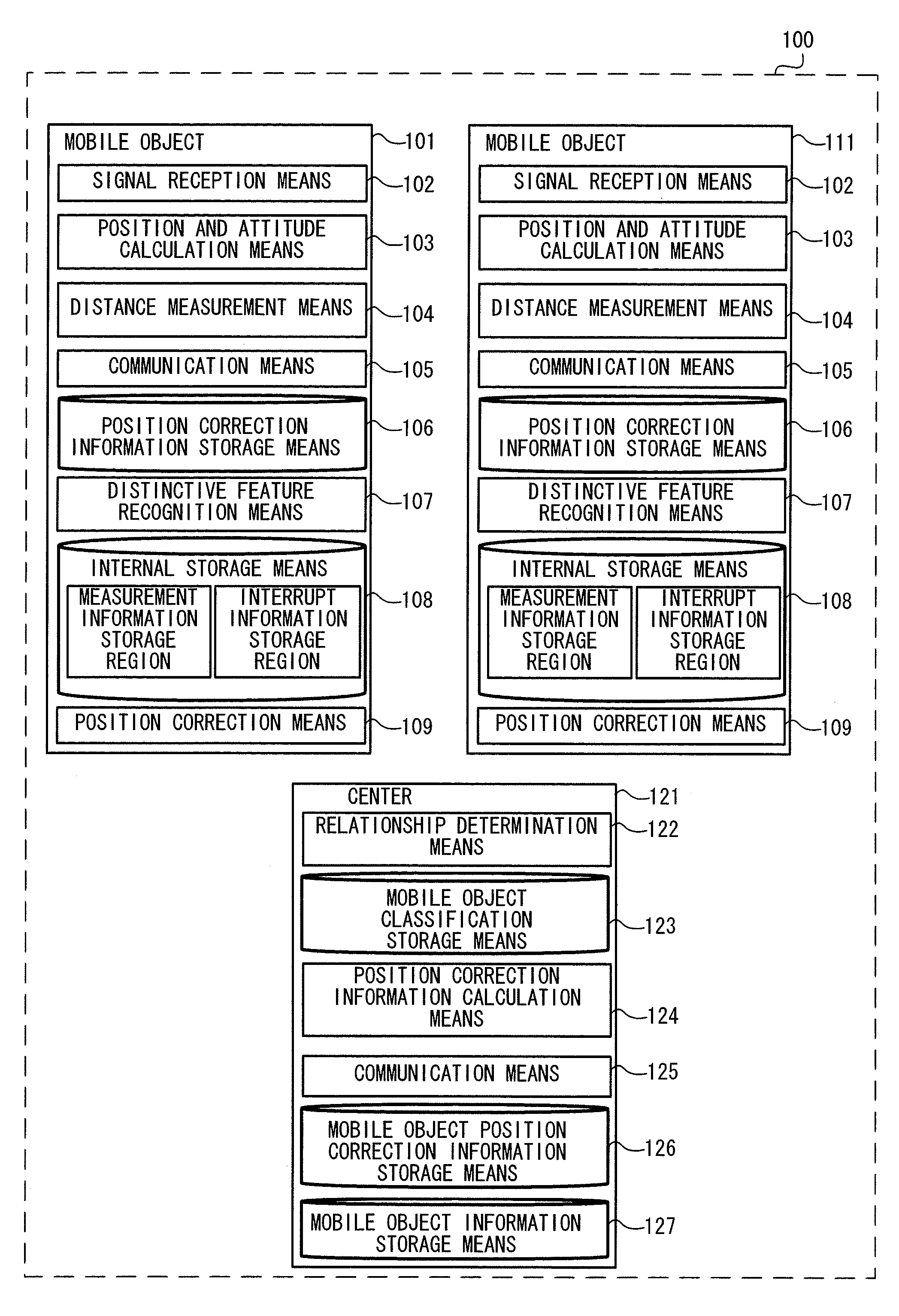
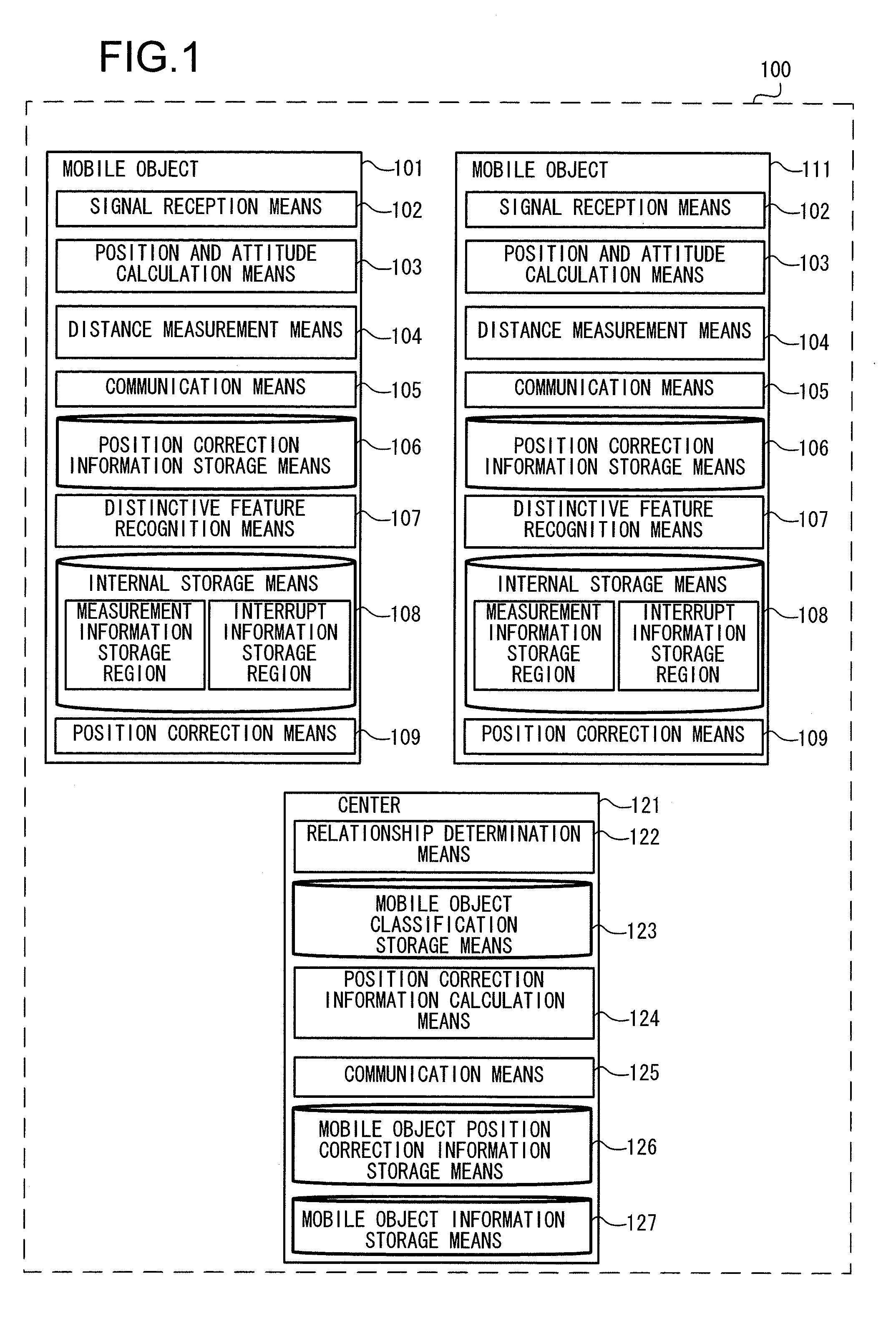
[0027]FIG. 1 is a structural diagram of a first embodiment of a location estimation system 100 according to the present invention. According to this first embodiment, the accuracy of position measurement is enhanced in an environment in which one or more specific mobile objects are shifting along a specific travel path such as in a mine or the like and in which it is possible to perform frequent communication between each of the mobile objects and a center, or between the mobile objects themselves.

[0028]This location estimation system 100 includes a plurality of mobile objects 101 and 111 and a center 121. It will be supposed that time synchronization to a common time reckoning has been established between the mobile objects 101 and 111 and the center 121. While FIG. 1 shows a simple example in which the location estimation system 100 includes the mobile object 101, the mobile object 111, and the center 121, the number of mobile objects could be greater.

[0029]The mobile object 101 i...

second embodiment

[0085]With the location estimation system 100 of the first embodiment described above, the relationship determination means 122 is provided in the center 121. However as a second embodiment, as shown in FIG. 9, a location estimation system 1100 will be explained in which a relationship determination means 1107 is provided to each of the mobile objects 1101. Since, in this second embodiment, each of the mobile objects 1101 includes a relationship determination means 1107, accordingly it becomes possible to perform position correction locally to the mobile objects 1101. Therefore it is possible to enhance the positional accuracy in a situation such as a big city environment, in which vehicles of various types come and go, and moreover in which there is a possibility of interruption of communication between the vehicles and the center.

[0086]This location estimation system 1100 according to the second embodiment is different from that of the first embodiment, in the aspect that, while i...


PUM


Abstract

A location estimation system includes: a position measurement unit that receives position measurement signals from a plurality of sources of emission, and calculates position information of a first mobile object; a distance measurement unit that measures a distance from the first mobile object and to a second mobile object; a relationship determination unit that determines presence or absence of a relationship between the first mobile object and the second mobile object based upon relative position of the second mobile object based upon the distance, and selects position measurement signals from sources of emission that are different from the sources of emission of the position measurement signals received by the first mobile object; a position correction unit that corrects a position of the first mobile object based upon the position measurement signals received by the first mobile object and the position measurement signals selected by the relationship determination means.

Description

INCORPORATION BY REFERENCE[0001]The disclosure of the following priority application is herein incorporated by reference: Japanese Patent Application No. 2010-039533 filed Feb. 25, 2010.BACKGROUND OF THE INVENTION[0002]1. Field of the Invention[0003]The present invention relates to a location estimation system that can estimate the position of a mobile object both indoors and outdoors.[0004]2. Description of Related Art[0005]Up until the present, in order to obtain the positions of a plurality of mobile objects with good accuracy, various methods have been proposed that employ information relating to the plurality of mobile objects. For example in Japanese Laid-Open Patent Publication 2003-337029 there is proposed a device that calculates the relative positional relationship between one mobile object and another mobile object accurately by utilizing the satellite signals from the per se known GPS (Global Positioning System), and that maps the positions of those mobile objects upon a...

Claims


Application Information

Patent Timeline
IPC IPC(8): H04W24/00
CPCG01S5/0072G01S19/46G01S19/40G01S5/021
Inventor BANDO, MIKIOTANAKA, KATSUAKIKAWAMATA, YUKIHIROAOKI, TOSHIYUKI
Owner HITACHI LTD
Why Eureka
Try Eureka