Combustion state estimating apparatus for internal combustion engine

a technology of combustion engine and estimating apparatus, which is applied in the direction of electrical control, process and machine control, instruments, etc., can solve the problems of complex process for calculating average values, complex deviation amount, and inability to detect angular acceleration that does not always agree with the state of combustion

Inactive Publication Date: 2006-01-31
TOYOTA JIDOSHA KK
View PDF17 Cites 35 Cited by
  • Summary
  • Abstract
  • Description
  • Claims
  • Application Information

AI Technical Summary

Benefits of technology

[0010]The invention has been accomplished in view of the aforementioned problems. The invention provides a combustion state estimating apparatus for an internal combustion engine which is capable of estimating the state of combustion of the internal combustion engine with high precision by minimizing the effect of factors or information other than the information related to the state of combustion.
[0012]In the combustion state estimating apparatus for an internal combustion engine constructed as described above, the state of combustion is estimated on the basis of the angular acceleration in an interval in which the average value of inertia torque caused by the reciprocating inertia mass of the internal combustion engine is substantially zero. Therefore, the combustion state estimating apparatus excludes the effect that the inertia torque caused by the reciprocating inertia mass has on the angular acceleration. Hence, the apparatus allows precise estimation of the state of combustion based on the angular acceleration.

Problems solved by technology

Therefore, the detected angular acceleration does not always agree with the state of combustion.
Hence, in some cases, the state of combustion estimated from the angular acceleration includes an error.
Thus, the process for calculating the average values and the amount of deviation is complicated.
Therefore, a complicated and cumbersome process needs to be performed; for example, the threshold value used for determination is changed every time the operational condition changes.
Therefore, according to the aforementioned conventional method, it is impossible to provide an estimation of the state of combustion corresponding to various operational conditions of the engine, and it is difficult to estimate the state of combustion at an arbitrary timing assuming a real operation of the vehicle.
However, despite the fact that the value of friction torque changes dependent on time and other factors related to environments and the like, the aforementioned method of Patent Application Laid-open No. 11-294213 does not take the time-dependent change in friction torque into consideration, and therefore allows an error in the calculated friction torque in some cases.

Method used


Image

  • Combustion state estimating apparatus for internal combustion engine
  • Combustion state estimating apparatus for internal combustion engine
  • Combustion state estimating apparatus for internal combustion engine

Examples


embodiment 1

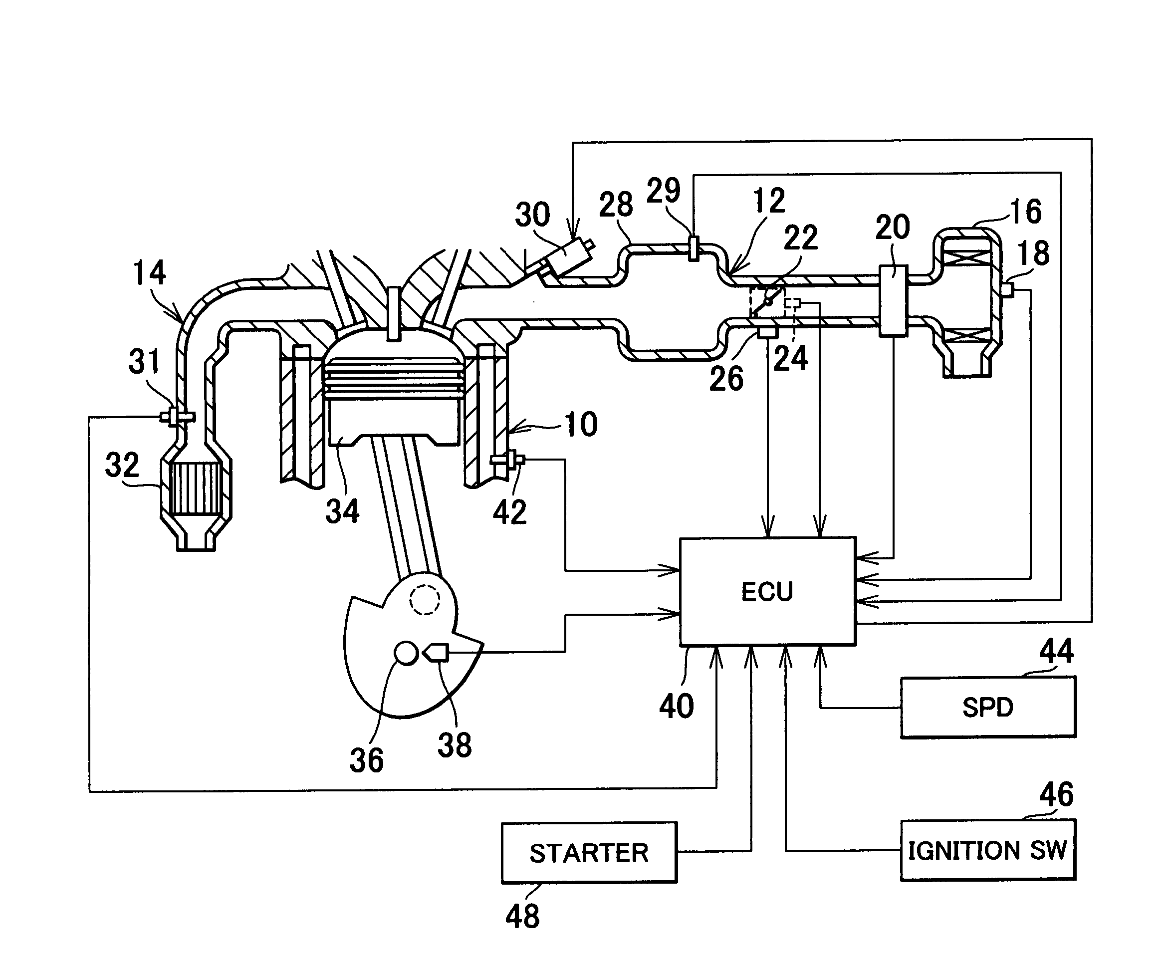
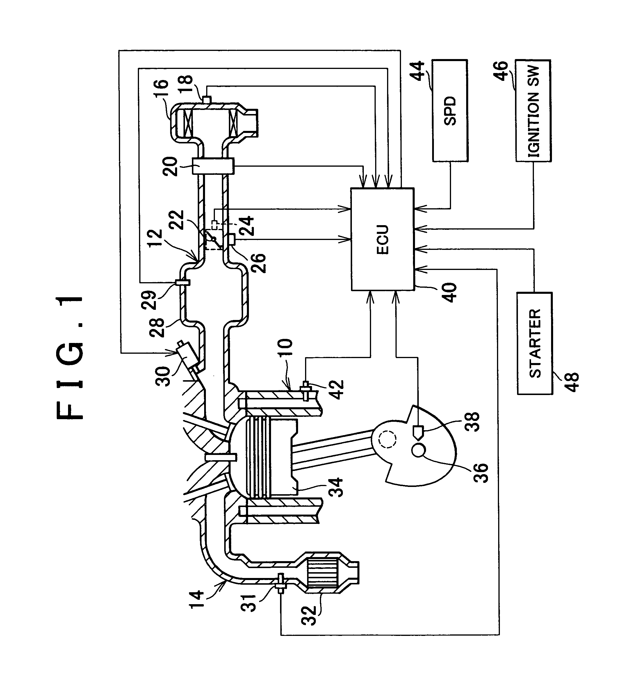
[0038]FIG. 1 is a diagram illustrating the structure of a combustion state estimating apparatus of an internal combustion engine of the invention and portions around the apparatus. An intake passageway 12 and an exhaust passageway 14 are connected to an internal combustion engine 10. An air filter 16 is provided in an upstream-side end portion of the intake passageway 12. An intake temperature sensor 18 for detecting the intake air temperature THA (i.e., the external air temperature) is attached to the air filter 16. The exhaust passageway 14 is provided with an exhaust emission control catalyst 32, and an exhaust pressure sensor 31 for detecting the exhaust pressure.

[0039]An air flow meter 20 is disposed downstream of the air filter 16. A throttle valve 22 is provided downstream of the air flow meter 20. The throttle valve 22 is formed by, for example, an electronic throttle valve. The degree of opening of the throttle valve 22 is controlled on the basis of a command from an ECU 4...

third embodiment

[0125]The procedure in the third embodiment will be described with reference to a flowchart shown in FIG. 14. First in step S31, the fuel injection from the fuel injection valve 30 is stopped and the ignition of fuel is stopped. Specifically, the fuel injection and the ignition are stopped within a single explosion stroke in an interval for calculation of the lost torque Tac.

[0126]In step S32, it is determined whether the present crank angle position coincides with the timing to calculate the lost torque Tac. Specifically, it is determined whether the present crank angle is in either the state where the crank angle is equal to or greater than TDC+10° or the state where the crank angle is equal to or greater than BDC+10°. If the present crank angle coincides with the torque calculation timing, the process proceeds to step S33. If the present crank angle does not coincide with the torque calculation timing, the waiting occurs in step S32.

[0127]In step S33, parameters needed for the ca...

fourth embodiment

[0149] the actual friction torque Tfw is calculated while the pumping loss indicated in FIGS. 15B and 16B is taken into account. A method for calculating the torque Tipl(k) corresponding to the amount of pumping loss will be described below.

[0150]The torque Tipl(k) corresponding to the amount of pumping loss is an amount of work corresponding to the area S1 in FIG. 15B, and is calculated from the difference between the in-cylinder pressure PEXHAUST during the exhaust stroke and the in-cylinder pressure PINTAKE during the intake stroke. Normally, the in-cylinder pressure PINTAKE during the intake stroke can be represented by the intake pipe pressure Pm, and the in-cylinder pressure PEXHAUST is approximately equal to the atmospheric pressure (=PATMOSPHERIC) Therefore, the torque Tipl(k) corresponding to the amount of pumping loss can be calculated as a function of an average intake pipe pressure Pm(k) for a torque calculation interval (every 180° in crank angle) as in an equation (6)....


PUM


Abstract

A combustion state estimating apparatus for estimating the state of combustion in an internal combustion engine includes an angular acceleration calculator that calculates a crank angle acceleration, and a combustion state estimator that estimates the state of combustion in the internal combustion engine based on the crank angle acceleration in a crank angle interval in which an average value of inertia torque caused by a reciprocating inertia mass of the internal combustion engine is substantially zero. Thus, the combustion state estimating apparatus excludes the effect that the inertia torque caused by the reciprocating inertia mass has on the angular acceleration, and therefore is able to precisely estimate the state of combustion based on the angular acceleration.

Description

INCORPORATION BY REFERENCE[0001]The disclosure of Japanese Patent Applications No. 2002-258134 filed on Sep. 3, 2002, No. 2002-258145 filed on Sep. 3, 2002 and No. 2003-114529 Apr. 18, 2003 including the specification, drawings and abstract is incorporated herein by reference in its entirety.BACKGROUND OF THE INVENTION[0002]1. Field of the Invention[0003]The invention relates to a combustion state estimating apparatus for an internal combustion engine, and is applied to an apparatus that estimates the state of combustion from a parameter regarding rotation of a crankshaft.[0004]2. Description of the Related Art[0005]To detect the state of operation of an internal combustion engine, a method of detecting the rotation speed, the angular speed, the angular acceleration, etc. during operation of the engine is employed. For example, Japanese Patent Application Laid-open No. 9-303243 teaches a method in which an angular acceleration of an engine is detected with reference to two predeterm...

Claims


Application Information

Patent Timeline
Patent Type & Authority Patents(United States)
IPC IPC(8): G06G7/70F02D41/14F02D41/34
CPCF02D41/1498F02D41/0097F02D2200/1015F02D2200/1006F02D2200/1004F02D41/042F02D41/062F02D2200/1012
Inventor UEDA, KOICHI
Owner TOYOTA JIDOSHA KK
Why Eureka
Try Eureka