Hot forging feeding electric-joint manipulator and operating method thereof
A manipulator and hot forging technology, which is applied in the field of hot forging feeding electric joint manipulator, can solve the problems of large impact vibration, slow speed, fast speed, etc., and achieve the effect of reducing impact vibration
- Summary
- Abstract
- Description
- Claims
- Application Information
AI Technical Summary
Problems solved by technology
Method used
Image

Examples
Embodiment Construction
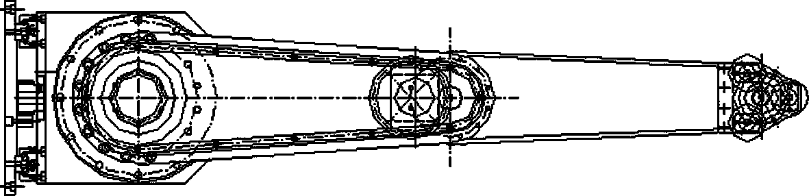
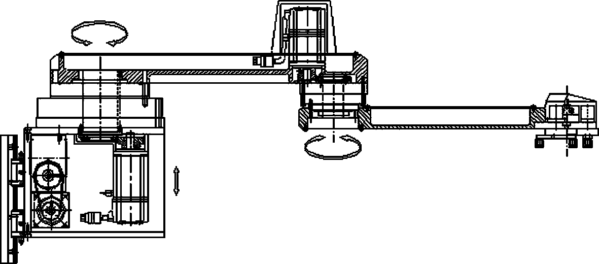
[0027] According to Figure 1 a Figure 4 As shown, a hot-forging electric joint manipulator for feeding materials includes: a large arm rotating component J1, a small arm rotating component J2, and a claw-type vertical up and down movement component J3; On the J1 shaft boom 5 of the component J1, the casing of the driving worm gear reducer 16 of the claw type vertical up and down movement component J3 is contained in the casing below of the driving worm gear reducer 4 of the boom rotating component J1.
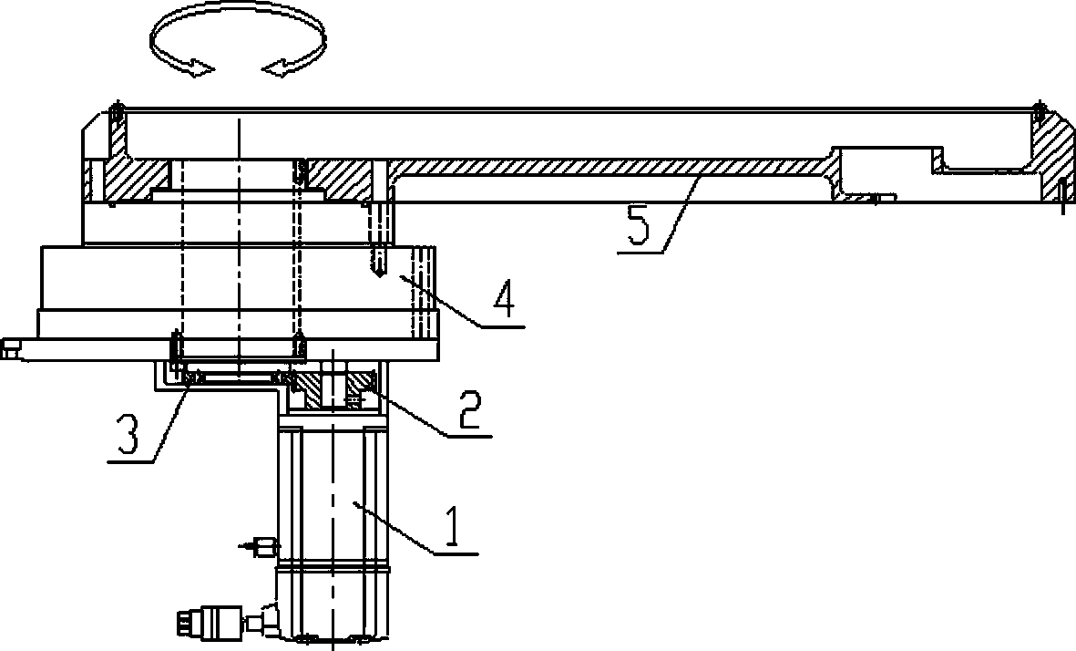
[0028] The boom rotating member J1 includes: a servo motor 1 fixed on the upper and lower platforms, a driving gear 2 is installed on the shaft of the servo motor 1, the driving gear 2 and the gear 3 mesh, and a harmonic reducer is installed above the gear 3 4. The harmonic reducer 4 is connected with the boom 5 of the J1 axis.
[0029] The small arm rotating member J2 includes: a servo motor 6 fixed at the end of the boom 5 of the J1 axis, a drive gear 7 is installed on ...
PUM
 Abstract
Description
Claims
Application Information