Inner geotextile bag sleeve valve pipe grouting construction method

A sleeve valve pipe grouting and construction method technology, which is applied in the field of geotechnical engineering grouting, can solve the problems of restricting cement diffusion space, complex construction technology, and easy occurrence of grouting, so as to improve engineering construction efficiency and reduce pipe jamming , The effect of simple construction method

Inactive Publication Date: 2014-07-02
HOHAI UNIV
View PDF7 Cites 5 Cited by
  • Summary
  • Abstract
  • Description
  • Claims
  • Application Information

AI Technical Summary

Problems solved by technology

[0004] However, the actual engineering application of this technology has gradually revealed that the construction process is relatively complex, and problems such as grouting and pipe jams are prone to occur during the grouting process: ①The single-hole grouting process of conventional sleeve valve pipe grouting is: drilling to design Depth→fill casing material→lower the sleeve valve tube→perform the first grouting→clean the residual grout in the sleeve valve tube→wait for coagulation→perform the second grouting
After the grouting of each hole, the sleeve valve pipe needs to be cleaned in time to facilitate the second grouting. The usual method is to insert the clean water pipe to the bottom of the sleeve valve pipe and rinse the grout in the pipe with clean water until the water flows out of the sleeve valve pipe mouth; ②During the grouting process, it often occurs that the grout flows out of the non-grouting pipes (cross grouting), which will lead to a large loss of grouting materials, and the cement grout flows into the sleeve valve pipes that have not been grouted. After cleaning, the grouting core tube cannot be inserted into the grouting core tube after the grout is hardened, resulting in the discarding of the sleeve valve tube, which will seriously affect the grouting process and grouting effect; Excessive grouting volume or excessive grouting pressure lead to excessive lateral movement of the surrounding soil or excessive uplift of the overlying soil layer, causing the sleeve valve pipe to deform (distort or disjoint), resulting in pipe jamming, and the grouting core pipe cannot be lowered into the Specify the grouting depth, which will cause a grouting blind area and seriously affect the grouting effect
[0005] Before the present invention, the Chinese patent (CN200910039943.4) disclosed a bag sleeve valve tube grouting technology that can avoid the phenomenon of slurry running and stringing and is conducive to the formation of piles. The technological process of this technology is: making the bag sleeve valve tube →Drill the hole to the designed depth→Insert the sleeve valve pipe with the cloth bag and drainage plate into the drill hole and center it→Pour casing material into the cloth bag→Segmented grouting after the casing material reaches the specified strength; the sleeve valve in this technology A cloth bag is put on the outside of the pipe to restrict the cement diffusion space, so that the grout forms continuous small-diameter cement piles in the cloth bag. The action mechanism of rock and soil mass can divide static pressure grouting into three forms: seepage grouting, compaction grouting and splitting grouting. From the perspective of the reinforcement mechanism of the bag sleeve valve pipe grouting technology, it can only achieve the effect of foundation reinforcement through compaction grouting, and cannot achieve the purpose of rock-soil splitting grouting and infiltration grouting, and the bag sleeve The valve pipe grouting technology is difficult to carry out the second repeated grouting due to the formation of bag piles with the sleeve valve pipe as the core in the rock and soil, thus greatly limiting the scope of popularization and application of this technology

Method used


Image

  • Inner geotextile bag sleeve valve pipe grouting construction method
  • Inner geotextile bag sleeve valve pipe grouting construction method

Examples


Embodiment Construction

[0031] Those skilled in the art can understand that, unless otherwise defined, all terms (including technical terms and scientific terms) used herein have the same meaning as commonly understood by those of ordinary skill in the art to which this invention belongs. It should also be understood that terms such as those defined in commonly used dictionaries should be understood to have a meaning consistent with the meaning in the context of the prior art, and will not be interpreted in an idealized or overly formal sense unless defined as herein explain.

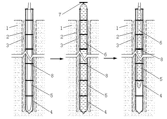
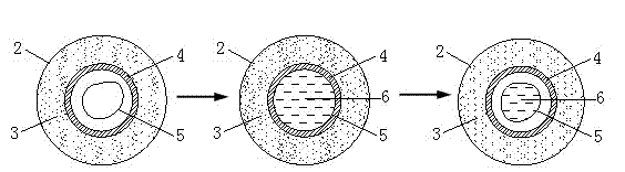
[0032] like figure 1 and 2 As shown, the geological drilling rig and other equipment are used to drill vertically in the foundation soil 1, and the mud retaining wall is formed into a hole with a diameter of 90-110 mm. After the drill hole 2 reaches the designed depth, the prepared casing material 3 is pumped to the The bottom of the hole is filled from bottom to top. After the casing material 3 is poured, immediately press...


PUM


Abstract

The invention discloses an inner geotextile bag sleeve valve pipe grouting construction method. On the basis of a conventional sleeve valve pipe grouting technology, a geotextile bag which can be filled with water and made by sewing impermeable geotextile is applied. After a sleeve valve pipe is inserted or first-time grouting is ended, the geotextile bag slightly longer than the sleeve valve pipe is guided to the bottom of the sleeve valve pipe through a cavity in the sleeve valve pipe, and clean water is poured into the geotextile bag till the whole cavity of the sleeve valve pipe is filled with clean water; when first-time grouting on holes to be injected with slurry starts or before repeated second-time grouting on the holes to be injected with slurry starts, the geotextile bag is taken out, and the remaining steps are the same as a conventional sleeve valve pipe grouting construction method. With the method, not only are the advantages of the conventional sleeve valve pipe grouting kept, but also the problem that slurry enters the sleeve valve pipe because of slurry mixing in the grouting process and the problem that the sleeve valve pipe is blocked because of deformation are solved, and meanwhile remaining slurry in the sleeve valve pipe can be removed effectively. The applied geotextile bag is easy to manufacture, low in cost, convenient to construct and capable of being repeatedly used and thus has very good application prospects.

Description

[0001] technical field [0002] The invention belongs to the technical field of grouting in geotechnical engineering, and relates to a soft soil foundation grouting reinforcement method, in particular to a grouting construction method for an inner bag sleeve valve pipe. Background technique [0003] Sleeve valve pipe grouting is to lower the sleeve valve pipe to the bottom of the hole through the drill hole, and adopt the segmental grouting process to make the grout spread evenly into the rock and soil mass under the grouting pressure. Because sleeve valve pipe grouting can carry out fixed depth, quantitative, fixed degree, fixed section, intermittent and repeated grouting, it has concentrated the advantages of compaction grouting, infiltration grouting and split grouting, and is currently used in soft soil foundations, tunnels It is widely used in projects such as anti-seepage and reinforcement of roadbed and embankment. [0004] However, the actual engineering application...

Claims


Application Information

Patent Timeline
Patent Type & Authority Applications(China)
IPC IPC(8): E02D15/04
Inventor 王安辉丁选明卢一为范玉明
Owner HOHAI UNIV
Why Eureka
Try Eureka