Truss system used for cold-formed thin-walled steel structure

A truss system, cold-formed thin-walled technology, applied in the field of truss systems, can solve problems such as local compression buckling damage, weak node stiffness, etc., to increase the force-bearing area, improve stiffness and strength, and enhance the ability to resist external forces and deformation Effect

Inactive Publication Date: 2014-07-02
SHANGHAI BESTSTEEL STEEL STRUCTURE BUILDING
View PDF0 Cites 3 Cited by
  • Summary
  • Abstract
  • Description
  • Claims
  • Application Information

AI Technical Summary

Problems solved by technology

This connection method concentrates the force on the end of the chord. Since the thickness of the member is thin and the stiffnes

Method used


Image

  • Truss system used for cold-formed thin-walled steel structure
  • Truss system used for cold-formed thin-walled steel structure
  • Truss system used for cold-formed thin-walled steel structure

Examples


Embodiment

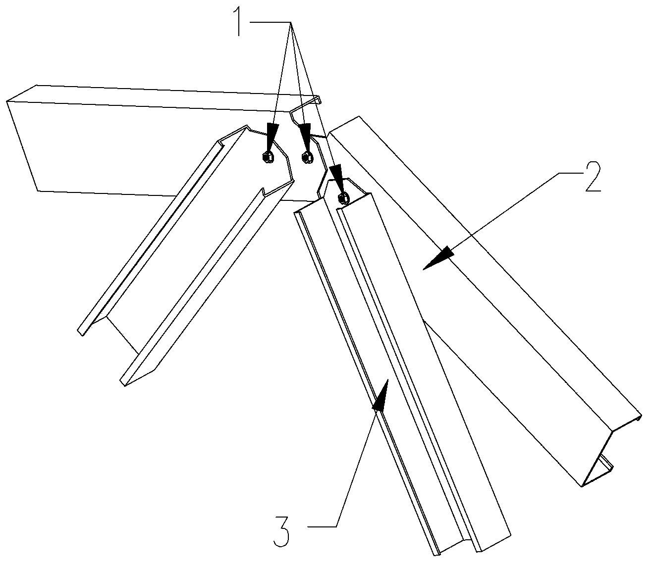
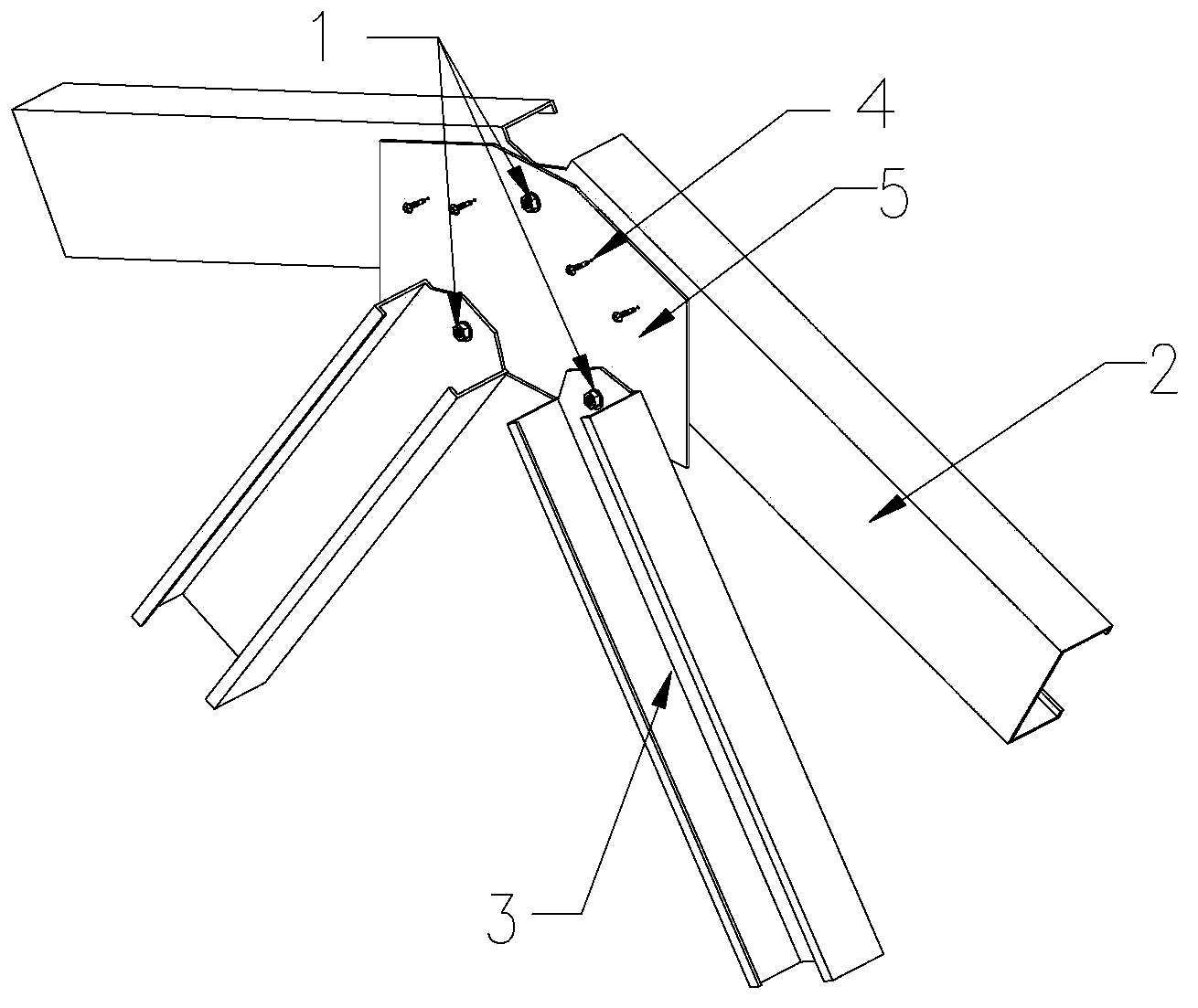
[0019] like figure 2 As shown, a truss system for cold-formed thin-walled steel structures includes truss chords 2, truss webs 3 and roof gussets 5, and the truss chords 2 and truss webs 3 are connected through the roof gussets 5 .

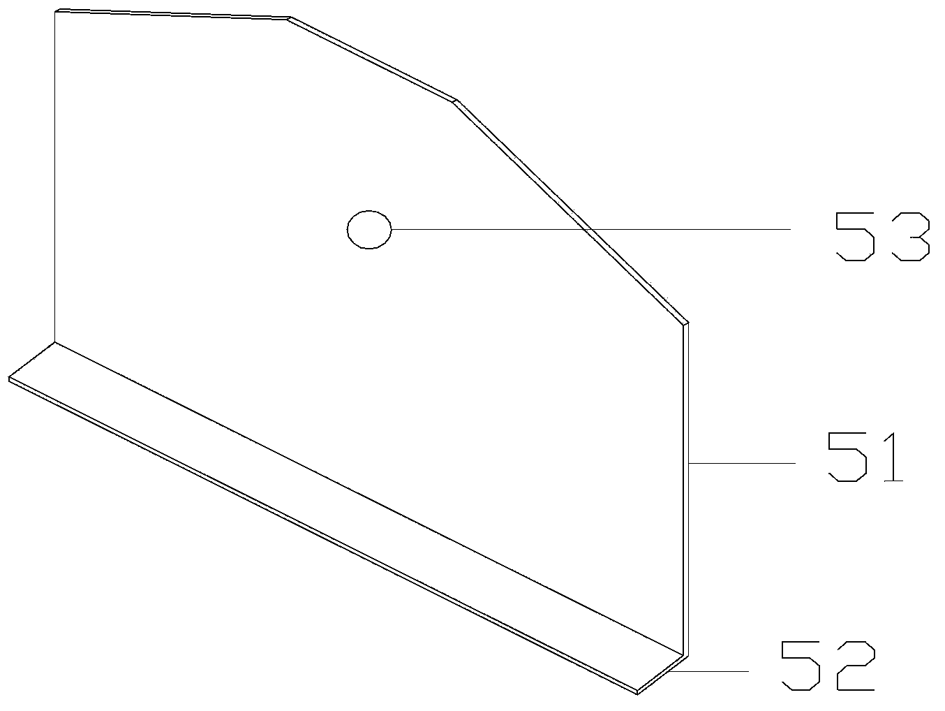
[0020] like image 3 As shown, the ridge gusset plate 5 includes an upper flat plate 51 and a lower folded edge 52, and the upper flat plate 51 and the lower folded edge 52 are connected at an angle of 90 degrees. The upper plate 51 is provided with an upper plate opening 53 .

[0021] There are two truss chords 2 , and the ends of the two truss chords 2 are connected by positioning structural bolts 1 , and then connected with the ridge gusset plate 5 through the upper plate opening 53 . The truss chord 2 is fixed on the upper plate 51 of the ridge gusset plate 5 by self-drilling screws 4 . 2 to 6 self-drilling screws can be provided as required, and 4 self-drilling screws are used in this embodiment. The truss web member 3 is fixed on the u...


PUM


Abstract

The invention relates to a truss system used for a cold-formed thin-walled steel structure. The truss system comprises a truss chord member and a truss web member and further comprises a ridge node plate, wherein the ridge node plate is respectively connected with the truss chord member and the truss web member. Compared with the prior art, the truss system has the advantages of being capable of improving truss system node rigidity and strength and the like.

Description

technical field [0001] The invention relates to a truss system, in particular to a truss system for cold-formed thin-walled steel structures. Background technique [0002] Under load, the truss members mainly bear axial tension or pressure, so that the strength of the material can be fully utilized. When the span is large, it can save material, reduce self-weight and increase rigidity compared with solid web beams, so it is suitable for large spans. Load-bearing structures and high-rise structures, such as roof trusses, bridges, transmission line towers, satellite launch towers, hydraulic gates, crane frames, etc. [0003] The traditional truss system used for the roof of cold-formed thin-walled steel structures such as figure 1 As shown, the truss system usually directly fixes the truss chord 2 and the truss web 3 with positioning structural bolts 1 at the ridge. This connection method concentrates the force on the end of the chord. Since the thickness of the member is th...

Claims


Application Information

Patent Timeline
IPC IPC(8): E04B7/06E04B1/342
Inventor 许金勇
Owner SHANGHAI BESTSTEEL STEEL STRUCTURE BUILDING
Why Eureka
Try Eureka