Gravel pump gravel filling method

A gravel pump and gravel filling technology, applied in the field of gravel filling with sand and gravel pumps, can solve the problems of bridging, time-consuming, poor accuracy of gravel throwing, etc. The effect of reducing pollution

Inactive Publication Date: 2014-07-02
XINJIANG TIANSHAN URANIUM IND CO LTD CNNC
View PDF2 Cites 9 Cited by
  • Summary
  • Abstract
  • Description
  • Claims
  • Application Information

AI Technical Summary

Problems solved by technology

[0003] The object of the present invention is to solve the technical problems of the prior art that the gravel-filling height is poor in accuracy and the gravel-filling pipe is prone

Method used


Image

  • Gravel pump gravel filling method

Examples


Embodiment Construction

[0015] The present invention will be further described below in conjunction with the accompanying drawings and embodiments.

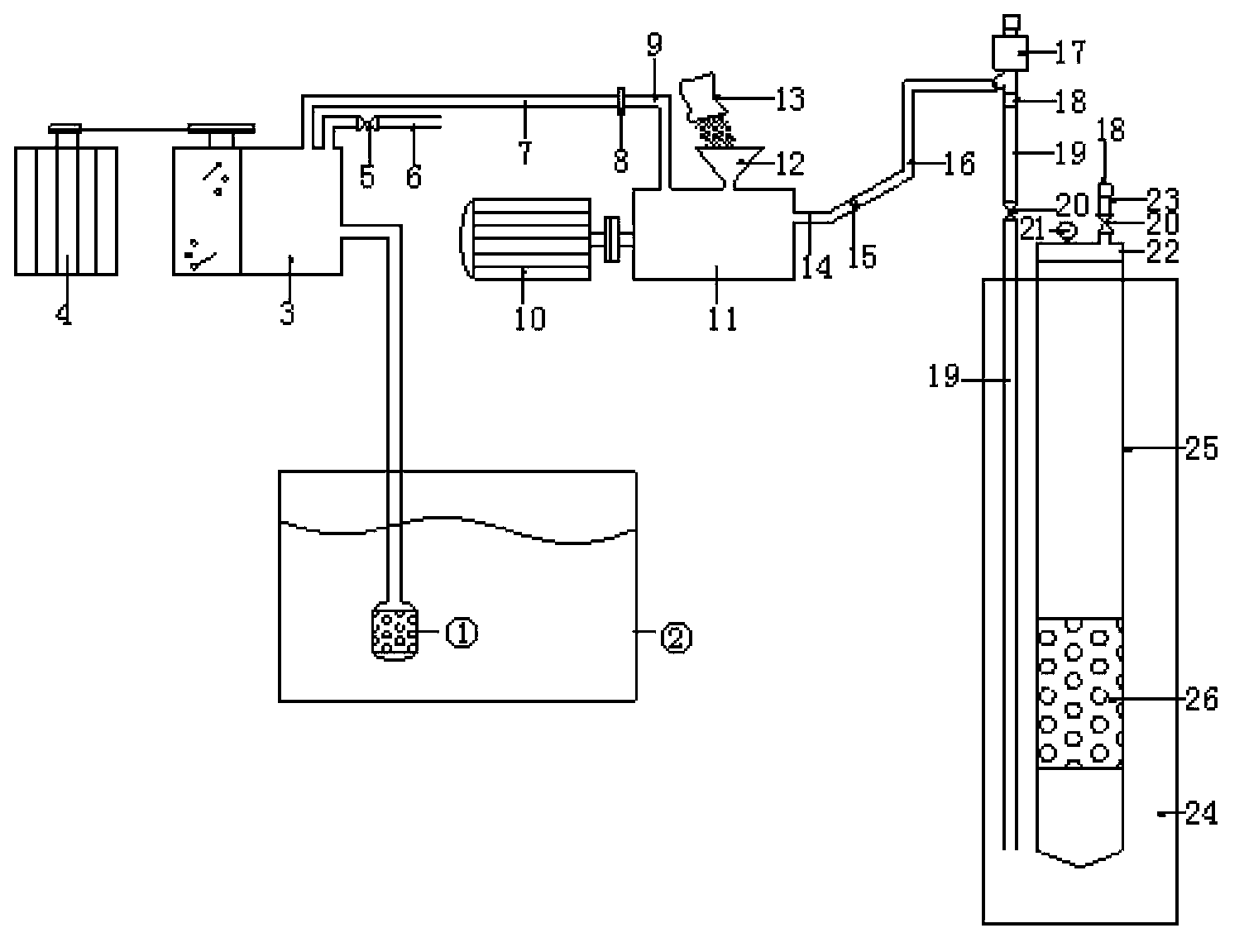
[0016] The invention provides a gravel filling method of a sand and gravel pump, which comprises the following steps in turn:

[0017] Step 1, installing the gravel throwing pipe 19 to a position 1 meter below the lower end of the filter 26;

[0018] Step 2, open the valve 5 of the mud pump 3, start the mud pump 3 to supply water to the gravel pump 11, and then start the gravel pump 11 to pump clean water into the backfill gravel space 24;

[0019] Step 3. After the top opening of the backfill gravel space 24 returns water, add the cleaned gravel 13 to the gravel funnel 12. When starting to put the gravel 13, first add a small amount of gravel 13 evenly. When the gravel 13 is conveyed evenly and smoothly Increase the throwing amount of gravel 13 again;

[0020] Step 4. When the gravel 13 is poured into the gravel funnel 12 for water gushing or the top...


PUM


Abstract

The invention belongs to the technical field of in-situ leaching mine gravel filling type structure drilling construction, and particularly relates to a gravel pump gravel filling method. According to the technical scheme, a gravel pump (11) is used for injecting water and throwing gravels into a gravel throwing pipe (19), when gravels are thrown, gravel (13) filling heights are measured, when the gravels (13) reach the required height position as designed, cement is used for sealing holes, and the gravel throwing pipe (19) is used for measuring the gravel filling height. Due to the fact that injection pressure of the gravel pump (11) is small, once the filling gravels (13) are flush with an opening of the gravel throwing pipe (19), the gravel pump (11) stops throwing gravels, water returns from a gravel throwing funnel (12), the gravel throwing height can be measured according to the principle, and quantification control of gravel throwing is achieved. By means of the technical scheme, gravel filling speed is high, efficiency is high, gravel filling position is precise, and pollution of mud on ore beds is reduced due to the fact that drilled holes are flushed when gravel is thrown.

Description

technical field [0001] The invention belongs to the technical field of gravel-filling structure drilling construction in in-situ leaching mines, and in particular relates to a gravel-filling method of a sand pump. Background technique [0002] In recent years, in-situ leaching mining technology has developed rapidly in low-grade sandstone-type uranium deposits, and drilling is an important way and link to realize in-situ leaching uranium production. In-situ leaching uranium mining injects the leaching solution into the ore layer through the liquid injection hole, and lifts the leaching solution to the surface through the liquid pumping hole. It is through these special "channels" of drilling that the in-situ leaching cycle process of continuous pumping and injection is realized. The gravel-filled drilling structure is a commonly used in-situ leaching drilling structure, and it has been widely used in water wells. However, the depth of water wells is usually between tens of m...

Claims


Application Information

Patent Timeline
IPC IPC(8): E21B43/04
Inventor 赵乔付何斌沈红伟王春霞王栋
Owner XINJIANG TIANSHAN URANIUM IND CO LTD CNNC
Why Eureka
Try Eureka