
Steam pressure reducing cooling valve

A desuperheating valve and steam technology, which is applied in sliding valves, valve details, safety valves, etc., can solve the problems that desuperheating water cannot be vaporized, water hammer, and the effect of desuperheating and vaporization is reduced, so as to ensure the decompression effect and shorten the equipment structure. , the effect of simple structure

Active Publication Date: 2014-07-02
东辰智能科技有限公司
View PDF7 Cites 11 Cited by
  • Summary
  • Abstract
  • Description
  • Claims
  • Application Information

AI Technical Summary

Problems solved by technology

[0005] 2. The opening of the temperature and pressure reducing valve increases or decreases with the change of the steam flow rate to ensure that the steam pressure behind the temperature and pressure reducing valve is constant. When the load (flow rate) decreases, due to the nozzle hole diameter and The quantity is fixed and cannot be adjusted, and the desuperheating and vaporization effect becomes worse; when the load (flow rate) is reduced to less than 1 / 3, because the pressure and temperature of the steam cannot be adjusted synchronously, the desuperheating and vaporization effect drops sharply, and a large amount of desuperheating water cannot be vaporized. As a result, the drainage capacity of the pipeline system will increase, resulting in different degrees of water hammer, and in severe cases, it will damage the structure of the temperature and pressure reducing valve body
[0006] 3. It takes a long time for desuperheating water to vaporize, and correspondingly makes the required structural length of the equipment longer

Method used


Image

  • Steam pressure reducing cooling valve
  • Steam pressure reducing cooling valve
  • Steam pressure reducing cooling valve

Examples


Embodiment Construction

[0025] The technical solution of the present invention will be further described in detail below in conjunction with the accompanying drawings.

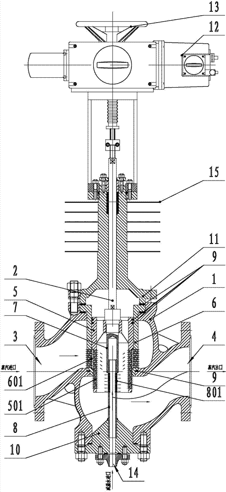
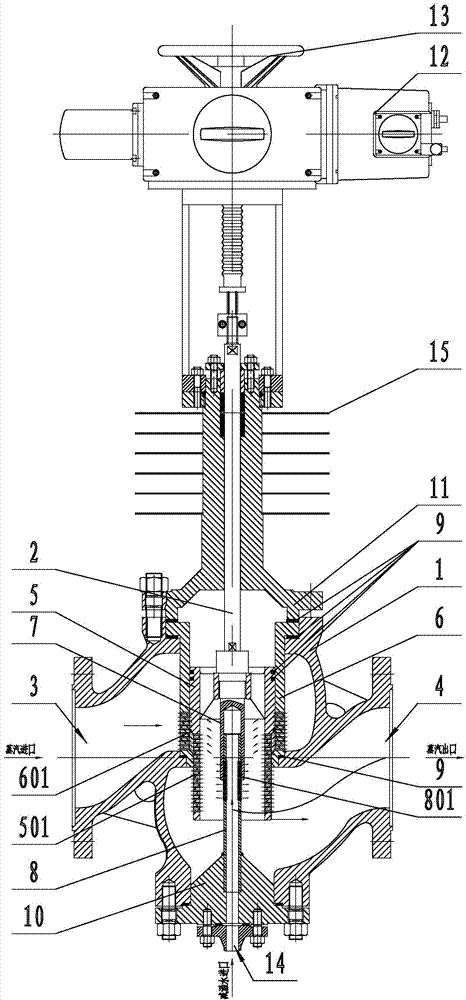
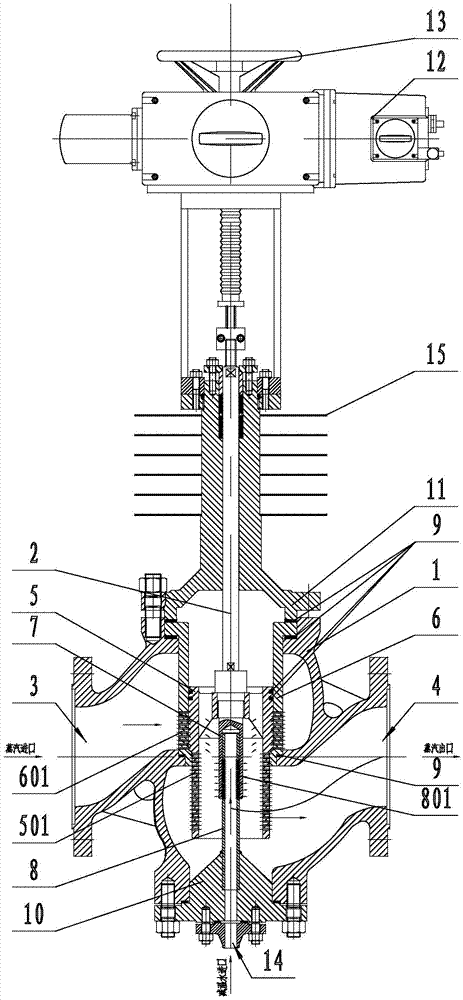
[0026] Such as figure 1 As shown, the present invention includes a valve body 1, a spool 2 disposed in the valve body 1, an inner sleeve 5, an outer sleeve 6 that is overlaid on the inner sleeve 5, an actuator that drives the spool 2 to move up and down, and the valve body 1 Steam inlet 3 and steam outlet 4 are respectively provided on the left and right sides, a plurality of second small holes 501 and first small holes 601 are respectively provided on the inner sleeve 5 and the outer sleeve 6, and the outer sleeve 6 is fixed on the valve body 1, cut off the passage of the steam inlet 3 into the valve, the first small hole 601 of the outer sleeve 6 communicates with the steam inlet 3, the inner sleeve 5 is fixed on the valve core 2 by fasteners, and the valve core 2 moves up and down The inner sleeve 5 is driven to move accordingly,...


PUM


Abstract

The invention provides a steam pressure reducing cooling valve, and relates to the field of the steam pressure reducing cooling valve. In the prior art, a steam pressure reducing cooling valve is complex in structure, slow in vaporization speed, large in length and large in size. The steam pressure reducing cooling valve is characterized in that an inner sleeve and an outer sleeve are further included, the inner sleeve and the outer sleeve are provided with multiple second small holes and first small holes respectively, the outer sleeve is fixed to a valve body, the first small holes of the outer sleeve are communicated with a steam inlet, the inner sleeve is fixed to a valve element through a fastener, the lower end of the valve element is provided with a sliding base, the sliding base is located in a cavity of the inner sleeve, the middle of the sliding base is provided with a connection cavity with a downward opening, the lower end of the valve body is provided with a nozzle matched with the connection cavity of the sliding base, the nozzle is hollow and cylindrical and is provided with multiple third small holes, the upper portion of the nozzle is connected with the connection cavity of the sliding base in a sliding mode, the number of the third small holes, covered with the inner wall of the connection cavity of the sliding base, of the nozzle is changed, the cavity of the inner sleeve is communicated with the second small holes and a steam outlet. According to the technical scheme, time for warm water vaporization is shortened, and the structural length of a traditional cooling device is reduced.

Description

technical field [0001] The invention relates to a steam decompression and temperature reduction valve. Background technique [0002] The existing traditional temperature and pressure reducing valve, the main representative model is WYS9 (6) 45 series, the composition structure WY9 (6) 45 type temperature and pressure reducing valve structure has two valve seats, such as figure 1 As shown, the valve disc is hollow and has a nozzle structure, and its desuperheating device is inside the desuperheating and decompressing valve, so that the desuperheating and depressurizing functions of the desuperheating and decompression device are completed in one body, and the structural length of the device is greatly shortened. Its characteristics are: regardless of whether the steam pressure fluctuates, the pressure behind the valve can always be kept basically unchanged; the flow of the desuperheating water is controlled by the electric control valve or the frequency conversion pump, and t...

Claims


Application Information

Patent Timeline
IPC IPC(8): F16K17/20
CPCF16K3/265F16K3/314F16K27/041F16K31/047F16K31/05F16K49/00
Inventor 罗林华
Owner 东辰智能科技有限公司
Features
  • Generate Ideas
  • Intellectual Property
  • Life Sciences
  • Materials
  • Tech Scout
  • Unparalleled Data Quality
  • Higher Quality Content
  • 60% Fewer Hallucinations
Learn More