
Pressure-relief system for gun fired cannon cartridges

a pressure relief system and cartridge technology, applied in the direction of ammunition projectiles, weapons, ammunition loading, etc., can solve the problems of significant damage, reach or exceed about 220° c., storage or transportation system, and impede the separation of the cartridge shell

Active Publication Date: 2012-08-16
NOSTROMO HLDG LLC
View PDF28 Cites 15 Cited by
  • Summary
  • Abstract
  • Description
  • Claims
  • Application Information

AI Technical Summary

Benefits of technology

[0012]It is an object of the invention to prevent separation of the cartridge shell from the projectile when there is a sharp increase in ambient temperature above the ignition temperature of the pyrotechnic igniter charge in a high pressure cartridge.
[0013]It is also an object of the invention is to prevent damage to the environment caused by a collection of many such cartridges, e.g., in a storage or transport container, upon sharp increase in ambient temperature such as caused by a fire.
[0014]It is a further object of the invention is to weaken the effect of the main charge after ignition of the igniter charge so that neither large pressure damage nor major mechanical damage results from unwanted ignition of high pressure cartridges.
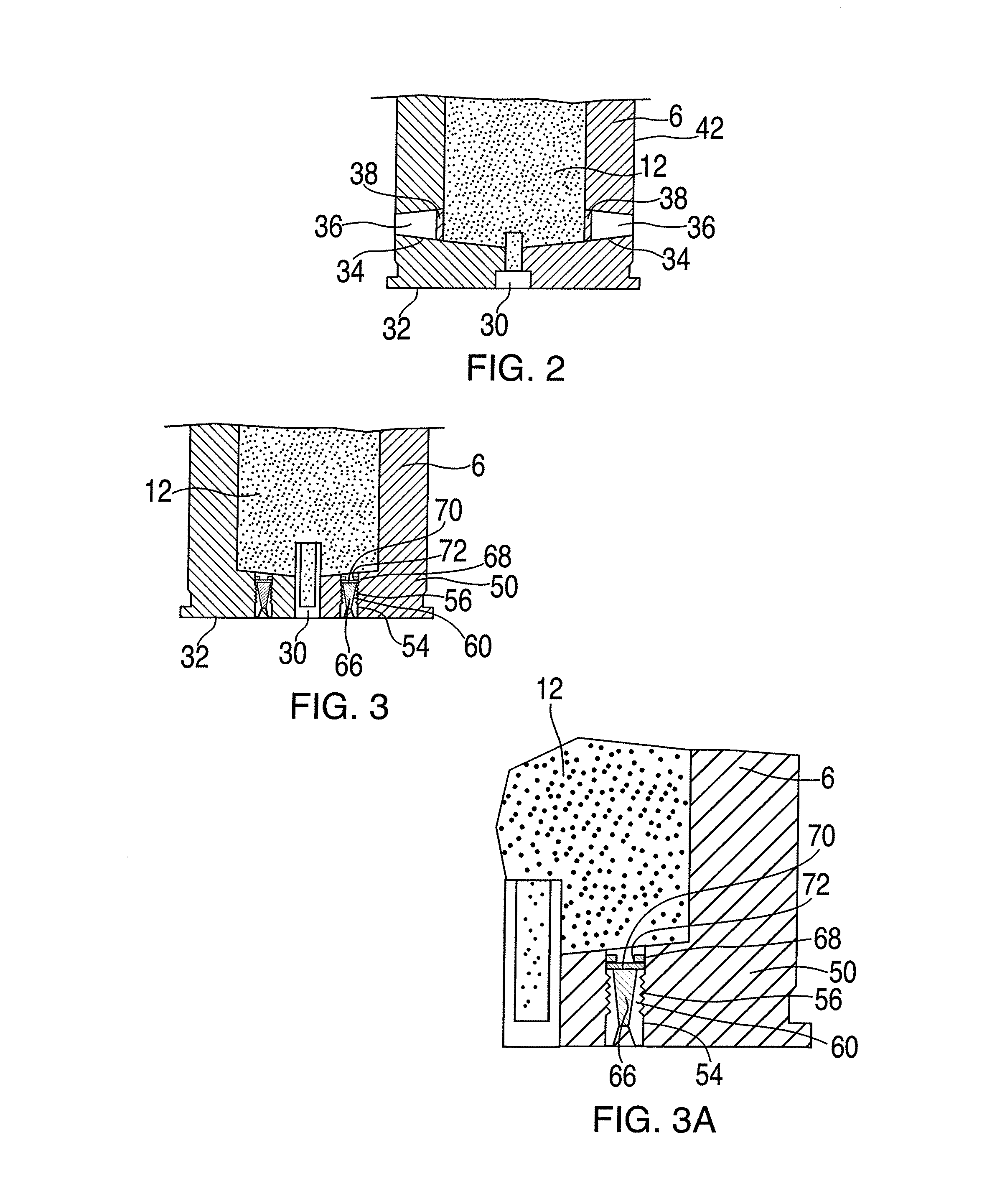
[0018]The rupturable support or relief members are positioned above or adjacent the fusible filler material, that is, between, the fusible filler material and the propulsive charge or propellant. More specifically, the fusible filler material is “capped” by, or enclosed in, non-fusible material of the support or relief member, such as a disk, a cap, or an annular ring. The resulting assembly, that is, the non-fusible metal relief member and the fusible filler material, provides a useful solution to provide support to the propellant when appropriate but prevent unwarranted ignition of higher pressure types of ammunition.
[0019]The pressure relief members disclosed herein are designed to fail when the propellant “outgases” or otherwise burns. In these circumstances, the relief members facilitate venting of propellant gases either (1) to preclude separation of the projectile from the cartridge shell or (2) to significantly reduce the energy (velocity) of a projectile. This disabling characteristic prevents inadvertent fuse function (because the “set-back energy” is inadequate to provide for fuse function), which prevents detonation and precludes possible loss of life.

Problems solved by technology

However, a fire in the storage or transport system during which temperatures reach or exceed about 220° C. presents a risk.
Significant damage may result simply from the quantity of exploded propulsive charges of a large number of cartridges.
The cartridge shell and projectile may cause great damage while flying apart, the cartridge shell and projectile acting as quasi projectiles.
Any storage or transport containers involved will be destroyed, whereby the separated cartridge shells and projectiles may endanger humans and cause major mechanical damage.
However, this technology may be limited in a variety of applications requiring higher working pressures, such as high speed, high velocity ammunitions.
More specifically, in some instances proper pressure integrity may not be achievable through the use of the geometric means and potential material selections described in the Haeselich patent.

Method used


Image

  • Pressure-relief system for gun fired cannon cartridges
  • Pressure-relief system for gun fired cannon cartridges
  • Pressure-relief system for gun fired cannon cartridges

Examples


Embodiment Construction

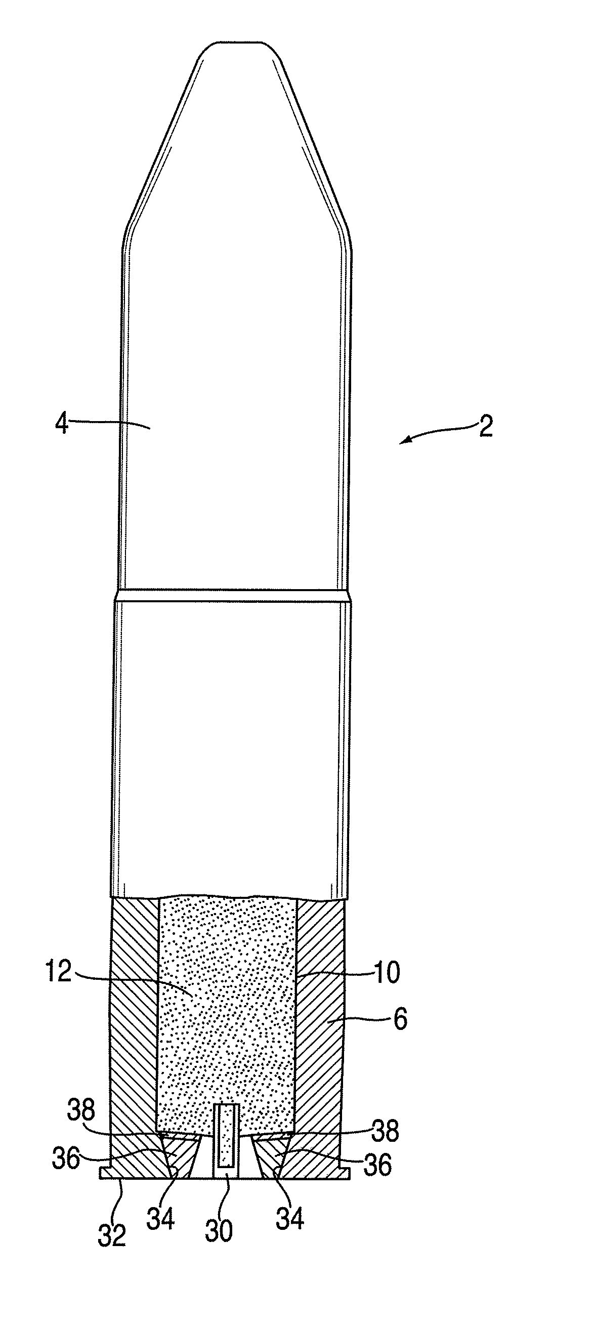
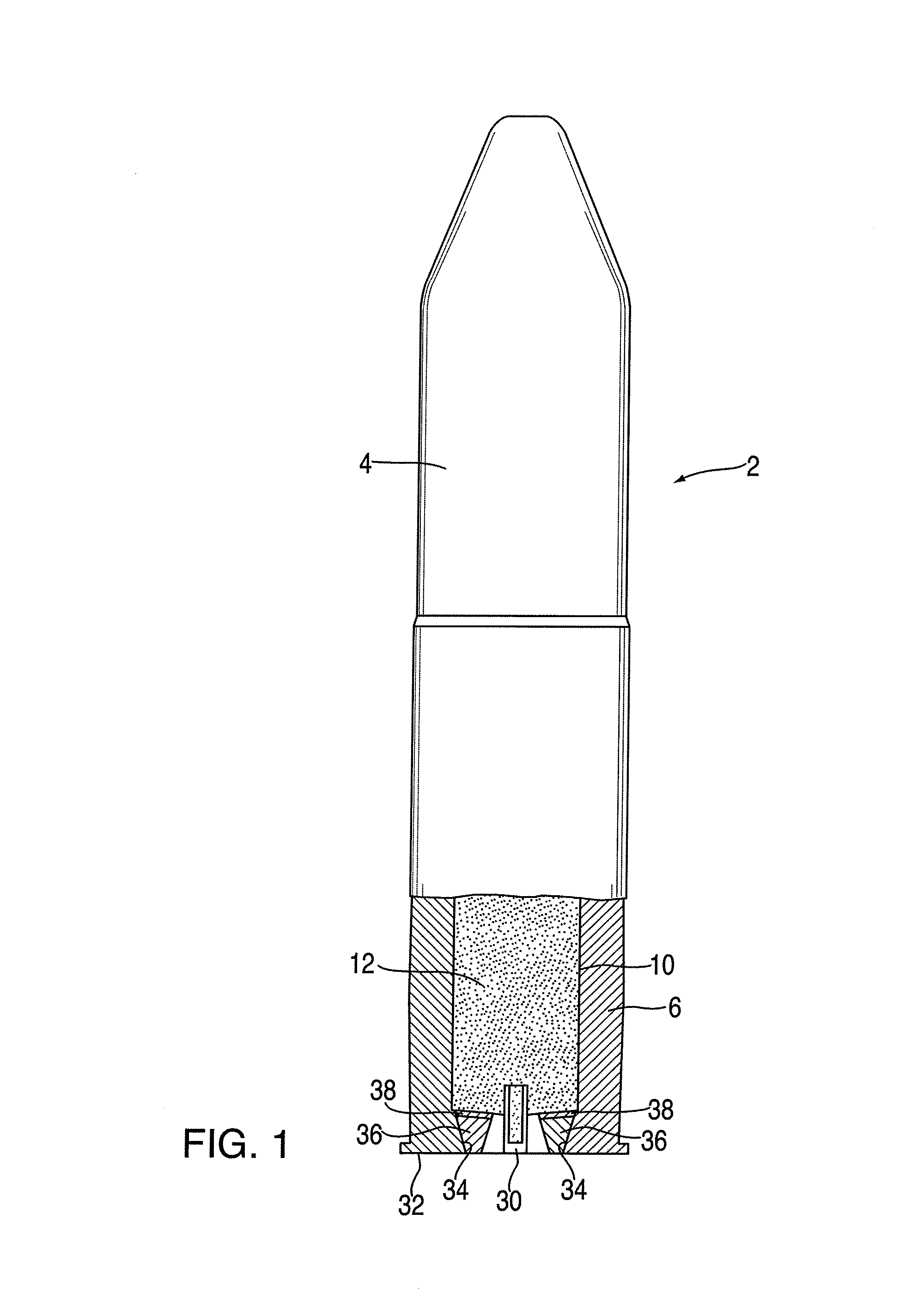
[0048]The preferred embodiments of the present invention will now be described with reference to FIGS. 1 to 3 of the drawings. Identical elements in the various figures are designated with the same reference numerals.

[0049]A cartridge munition 2 shown in FIG. 1 consists of a projectile 4 and a cartridge shell 6. Cartridge shell 6 includes a propulsion chamber 10 in which a propulsive charge 12 is positioned.

[0050]Cartridge 2 possesses a caliber of from 40 mm, for example, and is fired from a tube weapon (not shown) with a twist, for which purpose the projectile possesses a guide- or twist-band (indicated only).

[0051]Propulsive charge 12 is ignited pyrotechnically by means of an igniter cap 30 whereby igniter cap 30 is mounted in the center of the base 32 of cartridge shell 6.

[0052]Passages are provided between the propulsion chamber 10 and base 32 of cartridge shell 6. Here, conical channels 34 decrease in size in the direction of base 32 of cartridge shell 6. Channels 34 possess a ...


PUM


Abstract

A high velocity cartridge munition comprises a cartridge shell and a projectile inserted into it. A propulsion chamber within the cartridge shell receives a propulsive charge that may be ignited by a pyrotechnic igniter and that develops propulsive gases that act on the base of the projectile, driving it out of the cartridge shell. To prevent the pyrotechnic igniter from igniting spontaneously, and from igniting the propulsive charge due to the ambient temperature or because of a fire, which would cause the cartridge shell and projectile to be separated and fly apart, at least one exhaust channel between the propulsion chamber and the exterior of the cartridge shell is filled with a fusible material. The fusible material has a lower melting point than the ignition point of the igniter and of the propulsive charge. If the ambient temperature of the cartridge shell rises above the melting point of the fusible material, it melts, releasing the exhaust channels, so that, upon delayed ignition of the propulsive charge, it burns without pressure buildup, and the cartridge shell and projectile remain together. At least one non-fusible, rupturable member is positioned between the fusible material and the propulsive charge to provide mechanical support under normal conditions but to facilitate release of gases if the propulsive charge ignites.

Description

CROSS-REFERENCE TO RELATED APPLICATION[0001]This application is based upon and claims the priority of co-pending U.S. Provisional Patent Application Ser. No. 61 / 239,464, filed Sep. 3, 2009, incorporated herein in its entirety by reference.FIELD OF THE INVENTION[0002]This invention relates to a cartridge munition having a pressure relief system, particularly to a higher velocity, gun fired cannon cartridge.BACKGROUND OF THE INVENTION[0003]A cartridge munition comprises a cartridge shell and a projectile inserted into it, with the cartridge shell mechanically attached to the projectile. A propulsion chamber is provided at the base of the cartridge shell to receive a propulsive charge that, for example, may be ignited using an igniter cap. After ignition, propulsive gases from the propulsive charge act on the base of the projectile so that, upon release of the mechanical bond between cartridge shell and projectile, the projectile is driven out of the cartridge shell.[0004]Such a cartri...

Claims


Application Information

Patent Timeline
Patent Type & Authority Applications(United States)
IPC IPC(8): F42B5/26
CPCF42B39/20F42B5/02F42B5/025F42B5/26
Inventor SULLIVAN, KEVIN MICHAELDESMARAIS, BRIAN
Owner NOSTROMO HLDG LLC
Learn More