Position detector

A detector and detection object technology, applied in the direction of instruments, measuring devices, electrical devices, etc., can solve problems such as inappropriate

Inactive Publication Date: 2014-07-02
DENSO CORP
View PDF7 Cites 0 Cited by
  • Summary
  • Abstract
  • Description
  • Claims
  • Application Information

AI Technical Summary

Problems solved by technology

That is, for example, when high position detection accuracy is required at both ends of the detector movable range, a position detector having low position detection accuracy at both ends of the detector movable range is useful for some applications may not be suitable

Method used


Image

  • Position detector
  • Position detector
  • Position detector

Examples


no. 1 example )

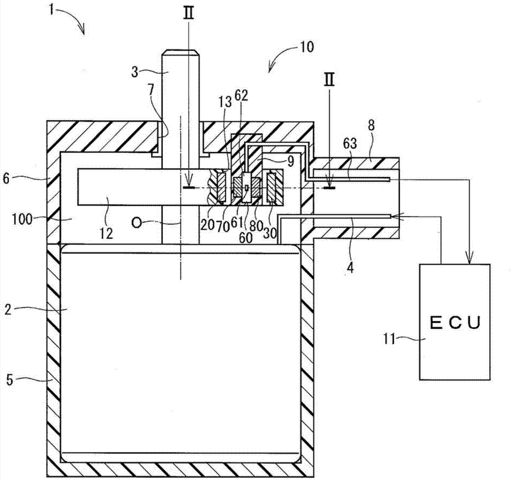
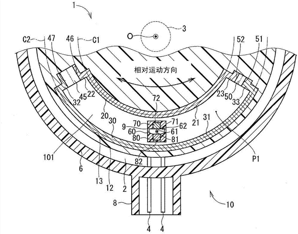
[0035] figure 1 with figure 2 The position detector and the actuator using the position detector in the first embodiment of the present invention are shown in .

[0036] For example, the actuator 1 is used as a driving power source for driving a throttle valve (throttle valve) of a vehicle (not shown). The actuator 1 is provided with a motor 2 , a housing 5 , a cover 6 , an electronic control unit (hereinafter, “ECU”) 11 , a rotating body 12 , a position detector 10 , and other components.

[0037] Such as figure 1 As shown, the motor 2 has an output shaft 3, a motor terminal 4 and the like. Electric power is supplied to the motor 2 via the motor terminal 4 . The motor 2 rotates by receiving electric power from the terminal 4 . The rotation of the motor 2 is output from an output shaft 3 . For example, the output shaft 3 is connected to a throttle valve through a gear set (not shown) or the like. Therefore, when the motor 2 rotates, the throttle valve also rotates.

...

no. 2 example )

[0086] exist Figure 6 The position detector in the second embodiment of the present disclosure is shown in . In the second embodiment, the first magnetic flux generator is different from the first magnetic flux generator in the first embodiment.

[0087] According to the second embodiment, the first magnetic flux generator has two magnets 40 . The magnet 40 is the magnet shown in the above comparative example. That is, magnet 40 and magnet 50 are each constructed to have the same magnet volume, same magnet type (e.g., neodymium magnet, ferromagnet, etc.), same material composition (e.g., if magnets 40, 50 are neodymium magnets, the same ratio of neodymium, iron, boron and the same content ratio of dysprosium, etc.; or if the magnets 40, 50 are ferromagnets, the same content ratio of barium, strontium, etc.) and permanent magnets of the same magnetization adjustment method.

[0088] Such as Figure 6 As shown in , in this embodiment, two magnets 40 are arranged in parallel b...

no. 3 example )

[0094] exist Figure 7 The position detector in the third embodiment of the present disclosure is shown in . According to the third embodiment, the position detector 10 has a third magnetic flux transmission part 53 . The third magnetic flux transmission part 53 is disposed at a position between the second end 23 of the first magnetic flux transmission part 20 and the second end 33 of the second magnetic flux transmission part 30 , and is connected with the first magnetic flux transmission part 20 The same material as that of the second magnetic flux transmission part 30 is made to be integrated with the first magnetic flux transmission part 20 and the second magnetic flux transmission part 30 . That is, in other words, the configuration of the position detector 10 in the third embodiment can be described as replacing the magnet 50 of the comparative example described above with the third magnetic flux transmission member 53 .

[0095] According to the present embodiment, th...


PUM


Abstract

A position detector includes a magnet disposed between first ends of first and second magnetic flux transmission parts and a magnet disposed between second ends of the first and second magnetic flux transmission parts. The position detector also includes a Hall IC that is positioned within a gap and moves relative to a rotating body. The Hall IC detects a density of the magnetic flux from the first and second magnetic flux transmission parts and outputs a signal according to the density of the magnetic flux passing therethrough in order to detect a position of a detection object. A minimum magnetic flux density position within the gap may be shifted to a position having the highest detection accuracy such that the position detection accuracy of the detection object is improved.

Description

technical field [0001] The present disclosure generally relates to a position detector for detecting the position of a detection object. Background technique [0002] In general, magnetic position detectors detect changes in the position of a detection object relative to a reference component. Magnetic position detectors may utilize magnetic flux generators such as magnets. For example, a position detector disclosed in Patent Document 1 (ie, Japanese Patent Laid-Open No. JP-A-H08-292004) is configured to form a magnetic flux transmission part having two magnets provided on a reference part. closed magnetic circuit. In this structure, the two magnets are respectively bound by the ends of the two magnetic flux transmission members facing each other. A spill magnetic flux flow from one transfer part to the other takes place in the gap between the respective ends of the two flux transfer parts. The magnetic flux density detector is configured to move together with the detect...

Claims


Application Information

Patent Timeline
IPC IPC(8): G01B7/00
CPCG01B7/30G01D5/145
Inventor 河野尚明山中哲尔
Owner DENSO CORP
Why Eureka
Try Eureka