Touch detection method, medium, touch control chip and touch control display device

a touch control and detection method technology, applied in the field of touch control, can solve the problems of affecting the accuracy of the original sample data indicated, introducing common-mode noise to the sense signal, and irregular changes in voltage difference,

Active Publication Date: 2022-10-04
SILEAD
View PDF3 Cites 0 Cited by
  • Summary
  • Abstract
  • Description
  • Claims
  • Application Information

AI Technical Summary

Benefits of technology

[0006]In order to overcome the problem of inaccurate touch location detection of a coding approach that may be caused by abnormalities in a dummy reference channel and thus to provide improved touch location detection accuracy, the present invention presents a touch detection method. The present invention also provides a touch control chip and a touch control display device.
[0033]The touch detection method of the present invention embodiment has the following advantages. First, through loading coded data in the drive channels, decoding data collected from the sense channels and performing differential processes between the decoded signals to form differential signals, a reduced common-mode signal, interference and noise can be achieved. Second, the differential signals are backward converted based on at least one reference channel that is not a static dummy channel but is a dynamically chosen reference channel determined as being without touch response based on a touch response detection. That is, the reference channel in the present invention is dynamically chosen. This can reduce the risk of inaccurate touch location inference caused by abnormalities of a dummy reference channel and helps improve touch location detection accuracy. Third, in one embodiment, multiple modes are provided, and when it is determined that a degree of non-uniformity of the differential signals does not exceed a prescribed value, a static reference mode that consume less power may be selected without performing touch response detection, in which a sense channel close to an end of the capacitive touch control device is directly taken as a reference channel. Fourth, the dynamic selection of reference channel(s) allows the sense channels close to ends of the capacitive touch control device to participate in touch response detection as other sense channels do, resulting in an expanded touch control range.

Problems solved by technology

However, in practice, the voltage difference may experience irregular changes, and a common-mode loop may result from contact between the operator and the capacitive touch control device, which may introduce common-mode noise to the sense signals.
Such noise may corrupt the accuracy of the original sample data indicated in the received sense signals, leading to inaccurate or frequent false touch location detection, absence of response and other problems.
However, this method causes a waste of the signal from the dummy channel, and if this reference signal is problematic, all the resulting signals for the touch control panel will be excessively strong or weak, leading to impaired accuracy of touch location detection.

Method used


Image

  • Touch detection method, medium, touch control chip and touch control display device
  • Touch detection method, medium, touch control chip and touch control display device
  • Touch detection method, medium, touch control chip and touch control display device

Examples


Embodiment Construction

[0044]The present invention will be described in greater detail by way of specific embodiments with reference to the accompanying drawings. Advantages and features of the present invention will become more apparent from the following description. Note that the figures are provided in a very simplified form not necessarily drawn to scale for the only purpose of helping to explain the disclosed embodiments in a more convenient and clearer way.

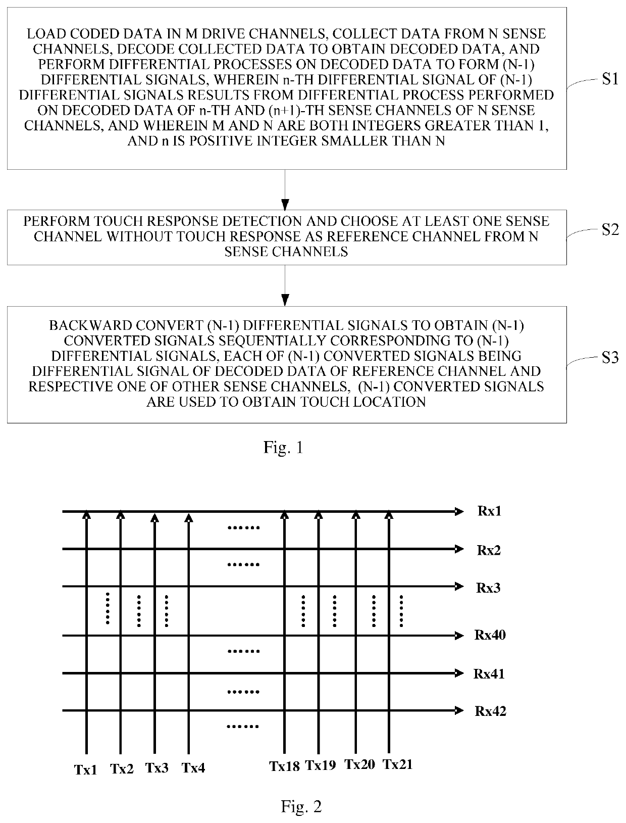
[0045]FIG. 1 is a flowchart of a touch detection method according to an embodiment of the present invention, which is implemented by a touch control chip. In an implementation, the touch control chip may be a control chip for a touch control display device. In an implementation, the touch detection method is implemented by hardware or software of a decoder in the touch control chip. As a non-limiting example, the decoder may be implemented as a digital signal processing (DSP) module or a microcontroller unit (MCU). Specifically, in the touch dete...


PUM


Abstract

A touch detection method, a touch control chip and a touch control display device are disclosed. In the touch detection method, coded data is loaded in drive channels and collected from sense channels. The collected data is decoded and subjected to differential processes. This results in a reduced common-mode signal, interference and noise. A touch response detection is carried out to choose at least one sense channel without touch response from sense channels as reference channel. This dynamically chosen reference channel reduces the risk of inaccurate touch location inference caused by abnormalities of static dummy reference channel and helps improve touch location detection accuracy, sense channels close to ends of capacitive touch control device are allowed to participate in touch response detection as other sense channels do, resulting in an expanded touch control range. The touch control chip and touch control display device all have similar advantages.

Description

CROSS-REFERENCES TO RELATED APPLICATION[0001]This application claims the priority of Chinese patent application number 202110779037.9, filed on Jul. 9, 2021, the entire contents of which are incorporated herein by reference.TECHNICAL FIELD[0002]The present invention relates to the field of touch control and, in particular, to a touch detection method, a touch control chip and a touch control display device.BACKGROUND[0003]Capacitive touch control is a touch control technique that is often used in existing intelligent terminals, in which a touch control chip scans drive electrodes and sense electrodes in a capacitive touch control device to determine a touch location. Sense channels in the capacitive touch control device may include drive channels (Tx) for sending drive signals transmitted from the touch control chip and sense channels (Rx) for receiving sense signals to be collected by the touch control chip. The touch control chip may determine the touch location from output data f...

Claims


Application Information

Patent Timeline
Patent Type & Authority Patents(United States)
IPC IPC(8): G06F3/044G06F3/041
CPCG06F3/044G06F3/04166G06F3/0446G06F3/0418
Inventor ZHANG, WUKANGYANG, JUN
Owner SILEAD
Why Eureka
Try Eureka