Rotation load applying device for tail rotor shaft fatigue test

An application device and fatigue test technology, applied in the direction of machine gear/transmission mechanism testing, etc., can solve problems such as the load that cannot simulate the periodic change of rotating parts, and achieve the effect of true and accurate test results and wide application prospects.

Inactive Publication Date: 2014-07-02
CHINA HELICOPTER RES & DEV INST
View PDF6 Cites 31 Cited by
  • Summary
  • Abstract
  • Description
  • Claims
  • Application Information

AI Technical Summary

Problems solved by technology

[0003] Existing test devices of similar products use a single arm to load separately, which cannot simulate the periodically changing load of rotating parts

Method used


Image

  • Rotation load applying device for tail rotor shaft fatigue test
  • Rotation load applying device for tail rotor shaft fatigue test

Examples


Embodiment Construction

[0009] The present invention will be described in further detail below.

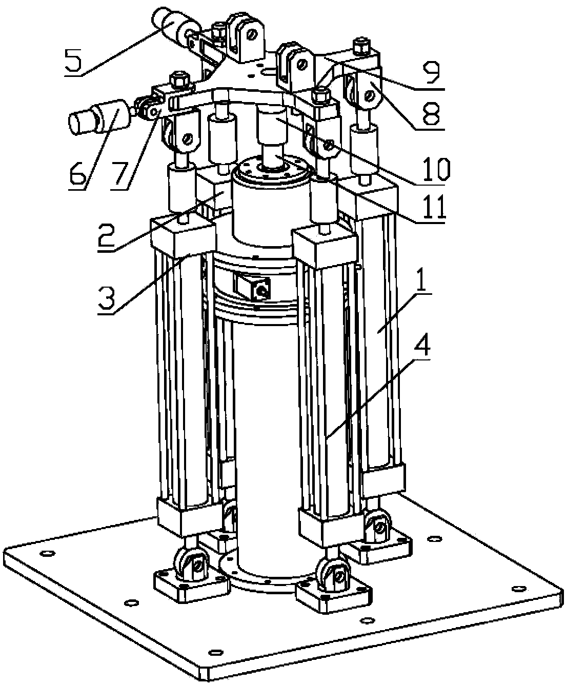
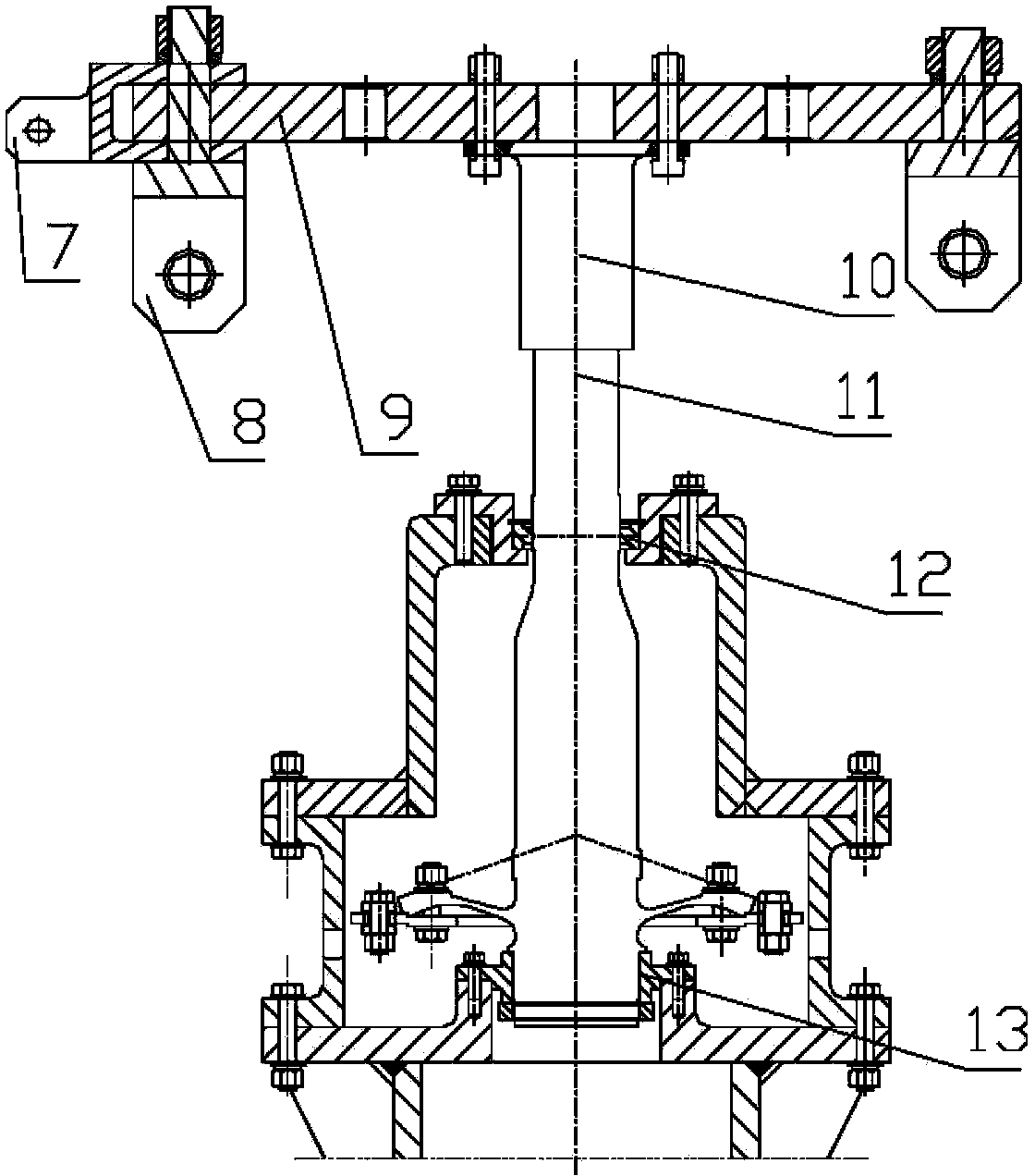
[0010] Such as figure 1 , 2 As shown, the present invention is specifically: the first hydraulic actuator 1, the second hydraulic actuator 2, the third hydraulic actuator 3, and the fourth hydraulic actuator 4 rotate the bending moment loading joint 8 and the loading plate 9 Connected and perpendicular to the disk surface of the loading disk 9, the first hydraulic actuator 1, the second hydraulic actuator 2, the third hydraulic actuator 3, and the fourth hydraulic actuator 4 are symmetrical to the tail rotor with the same force arm The shaft test piece 11 is arranged. The fifth hydraulic actuator 5 and the sixth hydraulic actuator 6 are connected to the two arms of the loading disk 9 with a difference of 90° through the rotating shear loading joint 7 and are parallel to the disk surface of the loading disk 9 . The tail rotor shaft test piece 11 is fixed with the test bench through the upper support be...


PUM


Abstract

The invention provides a rotation load applying device for a tail rotor shaft fatigue test so as to determine fatigue performance and weak parts of a tail rotor shaft and provide a basis for determining service life of the tail rotor shaft. The technical scheme of the invention is as follows: first, second, third and fourth hydraulic actuators are connected with a loading disc through rotation moment loading joints and are perpendicular to the disc surface of the loading disc; the first, second, third and fourth hydraulic actuators are symmetrically arranged around a tail rotor shaft test member with the same arm of force; a fifth hydraulic actuator and a sixth hydraulic actuator are connected through two support arms of a rotation shear loading joint and the loading disc which are 90 degrees from each other, and are parallel to the disc surface of the loading disc; the tail rotor shaft test member is secured to a test bed through an upper support bearing fake piece and a lower support bearing fake piece; the upper part of the tail rotor shaft test member is connected with the lower part of a tail decelerated output flange plate; and the upper part of the tail decelerated output plate is connected with the loading disc.

Description

technical field [0001] The invention belongs to the fatigue test technology of the tail rotor shaft of a helicopter, and relates to a rotating load applying device for the fatigue test of the tail rotor shaft. Background technique [0002] The single-rotor with tail rotor type is the most widely used form of helicopters in the world at present. The anti-torque of the main rotor is balanced and the heading control of the helicopter is realized through the rotation of the tail rotor shaft to drive the tail rotor to rotate. The tail rotor shaft is a typical complex moving part in the tail drive system of a helicopter. It bears the combined action of various loads such as rotational bending moment, torque, and tail rotor thrust during flight. Its force situation is complicated, and fatigue damage is the main failure mode. Its working reliability directly affects the flight safety of the helicopter. In order to ensure its good performance and reliability of use, its load and str...

Claims


Application Information

Patent Timeline
Patent Type & Authority Applications(China)
IPC IPC(8): G01M13/02
Inventor 李清蓉喻溅鉴罗伟
Owner CHINA HELICOPTER RES & DEV INST
Why Eureka
Try Eureka