

Operating state control method and device
A technology of working state and state, applied in the field of electronics, can solve problems such as waste of resources, and achieve the effect of reducing waste of resources and reducing battery life.
- Summary
- Abstract
- Description
- Claims
- Application Information
AI Technical Summary
Problems solved by technology
Method used
Image

Examples
Embodiment 1
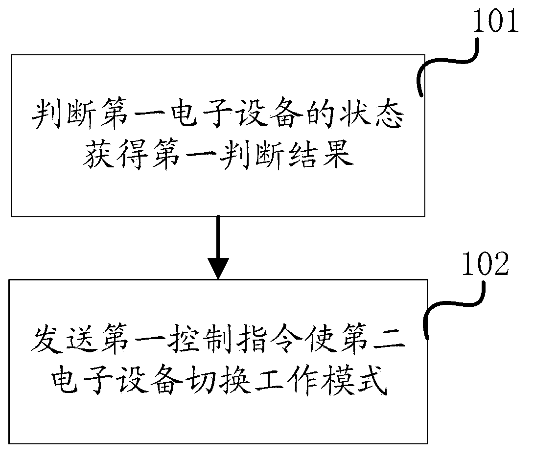
[0043] Embodiment one, as figure 1 As shown, a method for controlling the working state, the method is applied in the first electronic device, and the method includes the following steps:
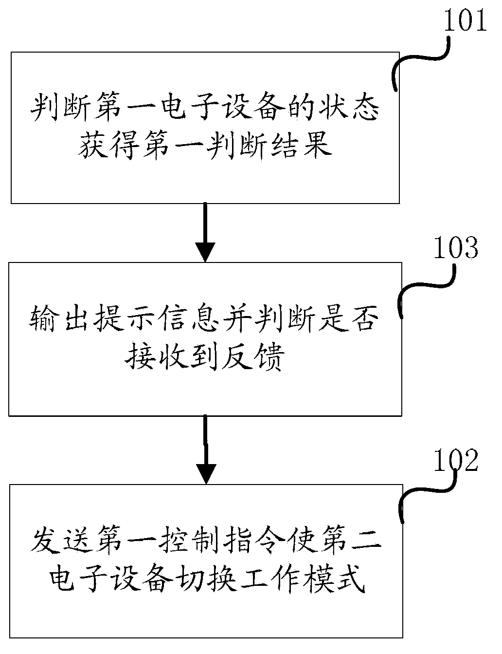
[0044] Step 101: When the first electronic device is connected to the second electronic device by wire or wirelessly, determine whether the first electronic device is in a charging state and / or whether it is between the second electronic device and the second electronic device The data transmission status of , and obtain the first judgment result;
[0045] Step 102: If the first judgment result shows that the first electronic device is not in the charging state and / or not in the data transmission state, then send a first control instruction to the second electronic device, so that all The second electronic device switches from the first working mode to the second working mode by executing the first control instruction, and the first power consumption corresponding to the first working mode...
Embodiment 2
[0077] Embodiment two, such as Figure 6 As shown, the embodiment of the present application also provides another method for controlling the working state, which is applied to the second electronic device, and includes the following steps:
[0078] Step 601: When the second electronic device is connected to the first electronic device in a wired or wireless manner, receive a first control instruction from the first electronic device;
[0079] Step 602: Execute the first control instruction to control the second electronic device to switch from the first working mode to the second working mode, the first power consumption of the first working mode is higher than that of the second working mode second power consumption;
[0080] Wherein, the first control instruction is specifically generated by the first electronic device when the first electronic device is not in the charging state and / or is not in the data transmission state with the second electronic device control instru...
PUM
 Abstract
Description
Claims
Application Information